Summary of The Digital Drone Synth
This article guides beginners in building a drone synthesizer using an Arduino Uno, a salvaged piano keybed, two oscillators, and a low-pass filter. The project focuses on creating full-sounding tones with overtones rather than complex features like ADSR envelopes or polyphony. It covers circuit design, matrix decoding for the keyboard, breadboard testing, and final soldering onto a perfboard.
Parts used in the Digital Drone Synth:
- Electronic piano keybed
- Arduino Uno
- LM324 Op Amp
- NE555P Timer
- TIP 41C Power Transistor
- TS Panel Mount Jack
- 2x 20k Potentiometer
- 1x 10k Potentiometer
- 4x 10k Resistors
- 2x 0.1uF Ceramic Capacitor
- 1x 10uF Electrolytic Capacitor
- Soldering Iron
- Solder
- Wire
- Perfboard
- DuPont style jumper wires
- Headers
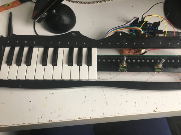
Making a hardware synthesizer is a really fun and rewarding experience. But usually with a lead synth you would want to implement ADSR envelopes, multiple adjustable oscillators, multiple types of filters for each, polyphony et cetera et cetera. Those aren’t conducive to a beginner project, but it definitely isn’t impossible to make something that sounds cool without all those bells and whistles. Drone synths are definitely an example of that, they’re usually used to “fill up the band” and make the sound more full and thus don’t need to be too complex, they just need to have a lot of overtones above the sound ( think of how distortion on a guitar makes it sound “fuller”, that’s because it has a lot of harmonics/overtones). This Instructable will go over how to make a drone synth controlled by a traditional piano keyboard, 2 oscillators (sound sources) and a low pass filter (removes the higher “harsher” frequencies).
Note: This project assumes an understanding on how to solder and the basics of electronics like current sourcing and sinking
Supplies
Parts – Prices are in CAD
1x Electronic piano keybed – No purchase link as mine was salvaged
1x Arduino Uno – $17.35
Side Note – any Arduino with at least 10 GPIO pins and PWM functionality will work, although for those the pins used in the code will not be accurate as the numbering is different.
1x LM324 Op Amp – $10.37
1x NE555P Timer – $2.18
1x TIP 41C Power Transistor – $7.82
1x TS Panel Mount Jack – $7.99
2x 20k Potentiometer+ 1x 10k Potentiometer – $8.63
4x 10k Resistors – $7.81
2x 0.1uF Ceramic Capacitor – $7.41
1x 10uF Electrolytic Capacitor – $7.56
Tools/Other Supplies (with what I used, you don’t have to use these)
Soldering Iron – Weller 25W
Solder – 0.8mm 63/37 rosin core solder
Wire – 30 AWG enameled copper wire
Perfboard – cut to 4cm x 4cm
12x DuPont style jumper wires
9x 0.1″ headers for the key matrix
Jumper wire for testing on a breadboard – DuPont style 0.1″ jumper cables
Step 1: the Design
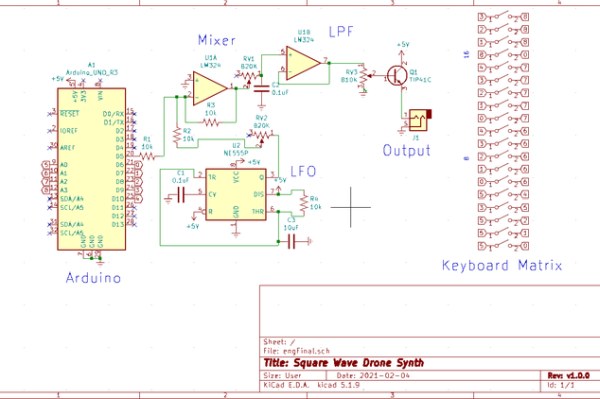
Oscillators
Oscillators are anything that generate sound, that sound usually then goes further to be filtered (removing frequencies) and attenuated (reduced in volume). The oscillators are the heart of a drone synth, Although usually I’m a big fan of completely analog synths and design, but for accurate pitches and tuning they usually require really high precision components and controlling the pitch of them with a control voltage (CV) gets really complicated really fast. There is a 555 timer in this which I will go over later, but it’s only used for modulating (changing the frequency) the main Arduino based oscillator. This is the reason there were chips like the cem3340 made especially for analog synths, the cem3340 has inbuilt CV circuitry and only requires those high precision components for tuning (and you don’t need to tune digital oscillators by the way). The Arduino here uses the tone library to generate a square wave on pin 5, a square wave goes high and low at a certain frequency and with a certain relation to how long there is a high compared to the low called the duty cycle. At 50% duty cycle the high and low periods are on at the same time for example. The 555 timer is configured in an astable mode (oscillates high and low, generating a square wave) which usually has a voltage divider at pin 7 which changes the discharging, since this isn’t connected in between resistors it gets straight 5 volts. The timing of the oscillation depends on the resistor-capacitor (RC) values used, the capacitor is the component that actually charges up with a voltage and the resistor current limits the capacitor which slows down the charging of the capacitor.
Low Pass Filter
A low pass filter removes anything above a certain frequency threshold. A RC low pass filter is used here, the capacitor can pass high frequencies depending on it’s capacity, it doesn’t allow lower frequencies because they are high for a longer period of time and thus fully charge up the capacitor faster. When a capacitor is fully charged it doesn’t allow any current to pass through it so those lower frequencies cannot pass. The capacitor connects through to ground so any high frequencies will find this path to ground and thus be removed from the signal. The resistor controls the current going to the capacitor and changing how fast it can charge up and by using a potentiometer that speed of charge and thus which frequencies can pass can be changed. This all then goes into an op amp voltage follower and a transistor which allow more current to be able to be sunk into the speaker.
Mixer
This uses a classic op amp mixer circuit. The resistors make a voltage divider and that controls how much feedback goes back into the inverting (negative) input of the op amp.
Code
The code is mostly for matrixing the keys, which will be explained more in step 2, aside from that it has an array of frequencies that correspond to pitches and when it knows which key on the keyboard has been pressed it calls the tone library to play that note on pin 5.
Step 2: Adapting This for Your Own Keyboard Matrix
I used a keyboard from a salvaged toy keyboard but I know you probably won’t have the same one when you’re making this, this is how to use any arbitrary key matrix. The way a keyboard matrix works is by having separate rows and columns, the columns (or rows for that matter) source current and if the switch is pressed down then current can pass through and that can be detected. This is shown in the GIF here, the letters are sourcing current while the numbers are checking if their input is high and thus if the switch is pressed down. These are steps I took to decode my personal keyboard
Key Matrix GIF by Oli Glaser on Stack Exchange – Link (CC BY-SA 3.0)
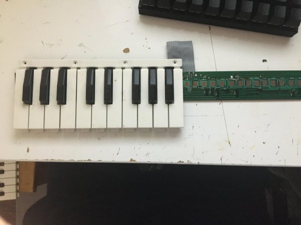
Step 2.1 – Isolate the PCB
If there are screws on the key-bed then remove them and remove the membrane on top of the PCB
Step 2.2 – Find Columns and Rows
In my keyboard’s case there were 5 rows per column, sopins 0-4 (when I talk about the pins here I mean the connections on the keyboard PCB) were rows and on the schematic you can see a pattern where you’ll have one pin on 5 keys (the first 5 keys are all connected to pin 5 for example) and the other side of those keys goes from 0-4
Step 2.3 – Change code for your key matrix
Now that you have your rows and columns, connect them to your Arduino! It doesn’t matter where as long as all the rows come one after the other and the columns come one after the other. If you happen to be using the same keyboard matrix as me, then pins 0-4 of the keyboard go to pins 6-10 of the Arduino and pins 5-9 of the keyboard matrix go to A0 through A4 of the Arduino.
Step 3: Testing on a Breadboard
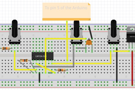
Before soldering everything up it’s a good idea to make sure everything works. The wiring diagram provides all the connections, it should be noted that the connections to the Key Matrix and Arduino aren’t shown, aside from pin 5 of the Arduino. Those other connections are shown in Step 2.
Wiring flow
For this project it’s easiest to wire from last to first, starting with the output TS jack. My personal TS jack wasn’t breadboard friendly so with 2 jumper wires and alligator clips, one from ground and one from the emitter of the transistor to the respective pins on the TS jack I was able to connect it to the rest of the breadboard circuit. The rest of the wiring can just be replicated from the wiring diagram.
The case
There were screw holes at the top of my keyboard case that fit the volume pot and the TS jack, along with space beside the key matrix to hot glue the potentiometers on to. As I’ve said I salvaged this toy keyboard but drilling 3/4 cm holes for the TS jack and volume pot along with 1 cm holes for the 555 volume pot and the LPF pot.
Step 4: Soldering!
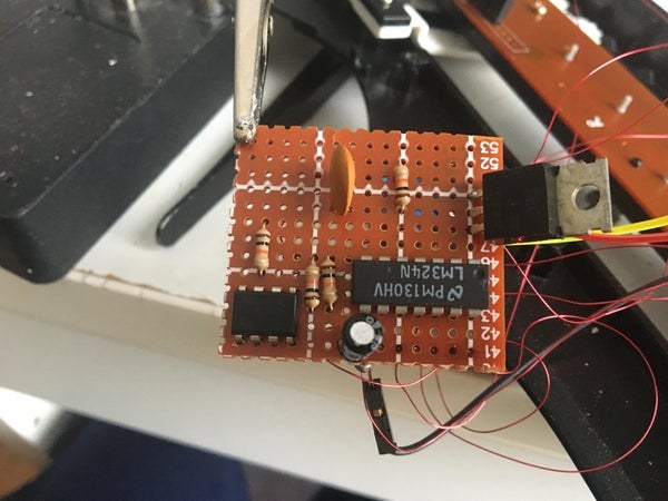
We’re almost done! Now that the synth works on a breadboard you can wire it up on a perfboard. I’ve found that removing one component / jumper wire at a time, putting it on the perfboard and connecting that according to the schematic found in Step 1 was really helpful for me not to get lost. One other tip is to have rails for 5v and ground. As you can see on the second picture there is a line of solder at the top, that is the ground rail and since many connections go to ground it’s helpful to have a bigger place where all of those things can go.
Step 5: Demo
With everything hopefully working now you have your own drone synth! If you are into music that uses electronic drones please try replicating some of your favorite songs, it’s a fulfilling experience like no other. Even if your preferred music doesn’t use these types of drones at least getting to play melodies of your choice on a piano keyboard on a synth you made was fun for me at least.
Source: The Digital Drone Synth
- What is the primary purpose of this drone synth project?
The project creates a simple sound generator to fill up a band by producing sounds with many overtones without complex features like polyphony. - Can I use an Arduino board other than the Uno?
Yes, any Arduino with at least 10 GPIO pins and PWM functionality will work, though pin numbering in the code may differ. - How does the 555 timer function in this circuit?
The 555 timer is configured in astable mode to modulate the frequency of the main Arduino-based oscillator. - How does the low pass filter remove frequencies?
The capacitor connects to ground, allowing high frequencies to find a path to ground and be removed while lower frequencies pass through. - What is the best way to adapt the code for a different keyboard matrix?
You must identify the rows and columns of your specific keyboard PCB and connect them sequentially to the Arduino, updating the code accordingly. - Why is it recommended to test on a breadboard first?
Testing on a breadboard ensures all connections work before permanently soldering components onto the perfboard. - How are the speaker current requirements handled in the design?
An op amp voltage follower and a transistor are used to allow more current to be sunk into the speaker. - Does the Arduino generate the square wave directly?
Yes, the Arduino uses the tone library to generate a square wave on pin 5 which serves as the main oscillator.