
Summary of Simple circuit indicates a low battery
This article describes a low-battery indicator circuit for an audio test instrument powered by four AA cells. Designed as a discrete solution, it uses a red LED as both the voltage reference and alarm indicator. The circuit monitors battery voltage by comparing the LED's turn-on threshold against a divided battery voltage at a transistor emitter. When the battery depletes, transistors Q1 and Q2 activate via positive feedback, brightly lighting the LED to signal a low battery condition while consuming minimal power in standby.
Parts used in the Low-Battery Indicator:
- Four AA cells
- Red LED
- Resistor R5
- Resistor R6
- Transistor Q1
- Resistor R1
- Resistor R2
- Transistor Q2
- Resistor R4
The Design Idea in Figure 1 indicates a low-battery condition in an audio test instrument that is powered by four AA cells. As the instrument was otherwise an all-discrete design, this same approach seemed more in keeping with the spirit of the project than the use of a single-sourced integrated circuit.
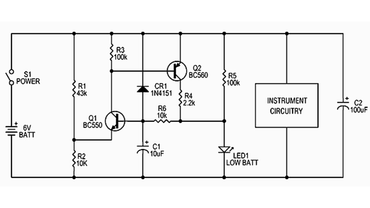
A garden-variety red LED serves as both the indicator and the voltage reference. A small current through R5 forward biases the LED, but its glow at this low value is barely visible, even in a dark room.
For this application, the LED proved to be a decent reference diode. It has a temperature coefficient that tracks fairly well with that of Q1, and the LED reaches its turn-on knee with less current than a zener diode needs to maintain its rated voltage. The circuit consumes only 160µA until it is triggered, at which point the LED runs at 2mA.
R5 biases the LED to its turn-on threshold, about 1.5V for a red one. This is applied through R6 to the base of Q1. R1 and R2 divide the battery voltage down to about 1.1V at the Q1 emitter. This 0.4V base-emitter differential is below the Q1 turn-on threshold.
As the battery is depleted, voltage across the LED remains constant, but the emitter voltage drops proportionally, and eventually Q1 begins to conduct. This draws base current from Q2, turning it on as well. Additional current to the LED through R4 raises the base voltage of Q1, and this positive feedback snaps the LED on smartly at the alarm threshold. When the LED lights, voltage across it rises to about 1.65V.
Read more: Simple circuit indicates a low battery
- How does the circuit indicate a low battery?
The circuit turns on transistors Q1 and Q2 when the battery voltage drops, causing the LED to light up smartly at the alarm threshold. - What serves as the voltage reference in this design?
A garden-variety red LED acts as both the indicator and the voltage reference diode. - Does the circuit consume significant power before triggering?
No, the circuit consumes only 160µA until it is triggered. - How is the base of Q1 biased?
R5 biases the LED to its turn-on threshold, which is then applied through R6 to the base of Q1. - Why was a discrete design chosen over an integrated circuit?
The project was otherwise an all-discrete design, so this approach fit the spirit of the project better than using a single-sourced IC. - What happens to the voltage across the LED when it lights up?
When the LED lights, the voltage across it rises to about 1.65V from its initial threshold of about 1.5V. - Can the LED be seen clearly at low current levels?
At the low value where it acts as a reference, the glow is barely visible even in a dark room. - What mechanism triggers the alarm state?
Positive feedback occurs as additional current to the LED raises the base voltage of Q1, snapping the LED on sharply.
