Summary of Rave Rover – Mobile Dance Stage
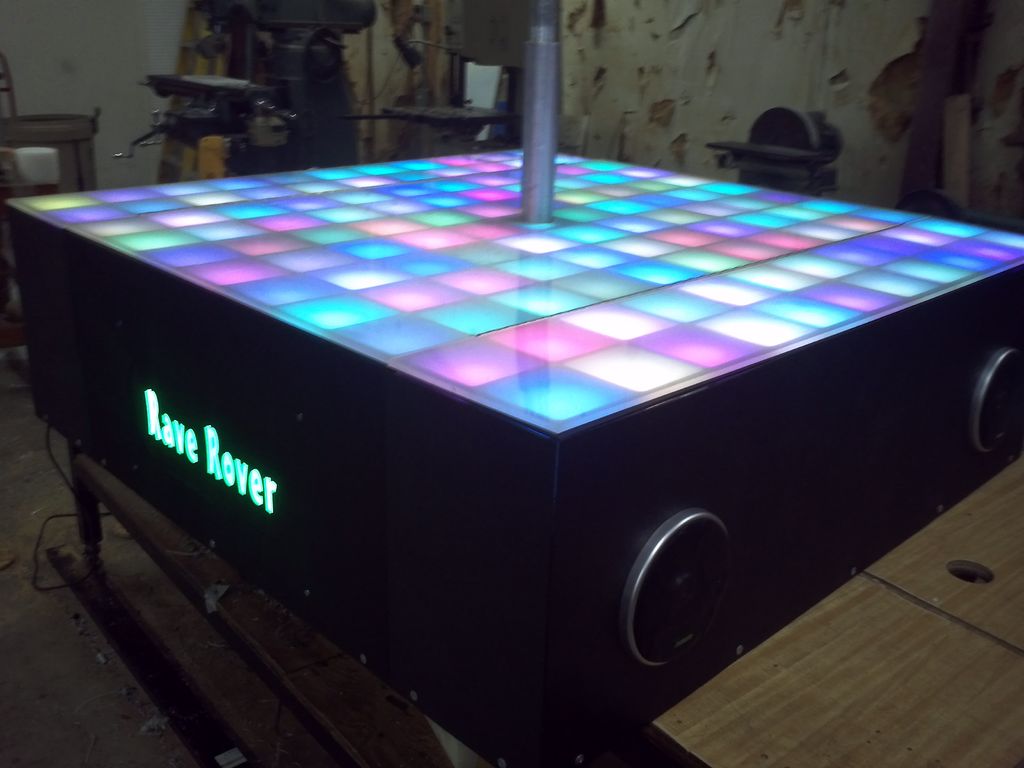
The Rave Rover is a portable, motorized dance platform designed for parties and raves. The build process involves designing with CAD, cutting ABS plastic frames using a CNC router, and assembling an 11x11 LED matrix controlled via SPI. The structure features a foldable design to fit through standard doors, utilizing aluminum tubing frames with drawer slides and pneumatic cylinders to raise and lower the stage. It includes a drive system with electric wheelchair motors, a subwoofer, amplifier, car radio, onboard PC, batteries, and an air compressor for operation.
Parts used in the Rave Rover:
- CNC Router
- Abs Plastic Sheet
- SMD5050 RGB LED Modules
- 3M Double Sided Tape
- Hot Glue
- White Translucent Plastic
- Aluminum Tubing (1x1x1/8 inch wall)
- L Brackets
- Drawer Slides
- Pneumatic Components
- Air Cylinders
- Solenoid
- Flow Restrictor
- Drive Motors
- 10 Inch Wheels
- Custom 10 Inch Subwoofer Box
- Amplifier
- Car Radio
- Onboard PC
- 12v 35Ah SLA Batteries
- Compressor
- Air Buffer Tank
- Arduino
- Power Switch
- Drive Speed Controllers
Step 1: Starting the Build
Step 2: Cutting Parts
From the CAD models, I was able to cut out the exact frame so that everything slides together and locks. I was also able to cut the top out of very thin ABS plastic sheet, which will give the ’rounded square’ look once the LEDs are installed and lit up.
The reason for using black plastic is to try to keep this project as light as possible, while at the same time not allowing any light to go between boxes.
Step 3: Fitting the floor
Step 4: Getting LEDs ready
Step 5: Installing the LEDs
The have to be wired all in series, so each row has to follow the row before it, and the ‘flow’ has to be correct, else you’ll not be able to light up some of the LEDs. The way these LEDs work is by sending them a serial string of data, the first LED takes it’s data off the top, and then sends the rest of the packet down the line, basically bit shifting the data stream. You can’t individually address the LEDs, but knowing where they are in the data stream, you can change their data in the stream itself.
Step 6: Adding the Frame
You can see how the slots in the rails we cut out are perfect for running the wires between the boxes.
Step 7: LED Color Check and Testing
For driving the LEDs, we’re using a simple Arduino by outputting data out of the SPI channel. Most of what you see is just random algorithms to make sure the colors are in working order and all of the pixels are working.
The top piece is white translucent plastic, works as a great diffuse panel as one is needed!
Step 8: Gathering More Materials
We picked up all of the aluminum (1x1x1/8″ wall) tubing, and cut it up to the sizes that we needed for the frames. While doing this we also picked up all of the pneumatic components which I’ll get into later in the build and explain WHY we need air cylinders on this project 🙂
Step 9: Frame Building
The next few steps will show the construction of these aluminum frames.
The original idea was to have all of the aluminum to be welded, but running out of time it was decided to use L brackets to bolt everything together. This seemed to be extremely strong and held together very well!
Step 10: Getting frames to fit…
In the video you can see how hard it is to control the air, I am using a standard blow nozzle and just shooting air into the input to make sure the frames will move and not be locked together. In the final version, I fixed the flow by adding in a flow restrictor on the solenoid input, make going up and down very smooth.
Step 11: Mounting Components
(2) Drive motors with 10″ Wheels (From Electric Wheel chair)
Custom 10″ Subwoofer Box
Amplifier for Subwoofer
Car Radio for powering mids/highs and taking computer input
Onboard PC
(2) 12v 35Ah SLA Batteries
Compressor
Air buffer tank
Electronics (Solenoid, drive speed controllers, Arduino, power switch, etc)
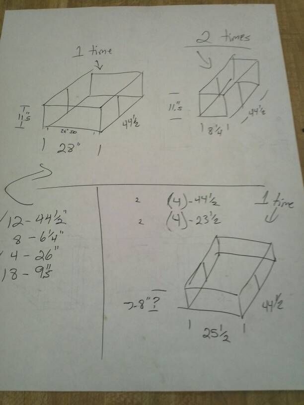
Now if you remember, the Main Stage frame was 28 x 44.5 inches, this means that the drive train frame was smaller, around 25×42″ where all of this stuff has to fit. What are we waiting for?! Lets get to it!
We start installing by necessity. Obviously we need to drive around, so the motors and wheels get mounted first! Next is the batteries (can’t forget those)..and then the next biggest item which was the subwoofer.
- How was the frame designed before building?
The layout was designed using CAD software to visualize how parts would fit together before purchasing materials. - What material was used for the floor panels?
Very thin black ABS plastic sheets were cut to create the top panel with a rounded square look. - How are the LEDs controlled?
The LED modules are controlled over an SPI interface where data is sent as a serial string and bit shifted down the line. - Why were L brackets used instead of welding?
L brackets were chosen to bolt the aluminum frames together because running out of time made welding impractical. - Can the stage fit through a standard door?
Yes, the foldable wings allow the main stage area to be driven through a standard 30 inch door opening when folded. - What mechanism raises and lowers the stage?
Drawer slides act as linear rails while air cylinders lift and lower the drive train frame relative to the main stage frame. - How was the air flow controlled for smooth movement?
A flow restrictor was added to the solenoid input to fix the airflow and ensure smooth up and down movement. - What drives the wheels on the Rave Rover?
The project uses two drive motors sourced from an electric wheelchair connected to 10 inch wheels.