Motivation
What to do you do when you have some Bare Conductive paint and some Philips Hue lightbulbs laying around? You paint a dimmer switch on your wall using conductive paint!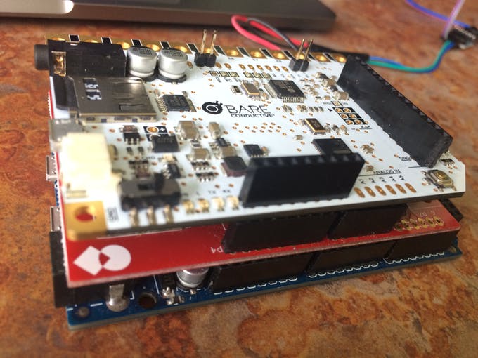
Getting Started
Some things you’ll need to get started:
- Arduino Due (or Zero)
- AnduinoWiFi shield (or another WiFi101 enabled Arduino)
Hardware
The Bare Conductive Touch Board actually contains an Arduino compatible MCU (the ATmega32u4), so although it’s stacked like a shield we’re actually using two different Arduino boards which communicate over serial UART with each other. There’s a touch interface sketch running on the touch board, and then the hueDino Philips Hue API client runs on the anduinoWiFi Due. Eventually this could all be condensed in size to run on a MKR1000 and a MPR121 breakout if size were a concern.
The touch Board is essentially an Arduino Leonardo with an onboard MPR121 capacitive touch sensor, SD card reader, and mp3 player with 1/8″ audio out.
WiFi Connectivity
You can test out a whole bunch of different painted circuits and touch interfaces using just the touch board. But when it comes time to internet connect your new interface slapping a WiFi shield on the ATmega32u4 isn’t quite going to cut it. B.C. also makes a touch interface board for the Raspberry Pi which helps make it a bit easier to internet connect your conductive paint designs.
Since the touch board can’t support WiFi this is why we’ve introduced the second Arduino Due paired with the anduinoWiFi This can now handle the Hue API communication between our Arduino and the local Philips Hue Bridge (which in turn controls the lights). It listens on a serial port for dimmer switch values sent by the touch board.
Let’s get things connected up!
Soldering and Wiring
Step 1
To connect the three main components I’ve soldered a stackable header to the power pins of the B.C. touch board. After removing the LCD screen from the anduinoWiFi shield (just spin off the nylon stand offs and pull up) you can stack it right on top. I’ve also soldered headers for the touch electrodes and for pins 10 and 11 which we’ll use for the Software Serial comms between the touch board and the Arduino Due.
Step 2
Once you’ve soldered the headers stack the touch board on top of the anduinoWiFi shield. Before stacking the shields on to the Due plug two wires into pins 18 and 19 Tx1 and Rx1. Either bend the pins or use a 90* degree header so the shield can still rest on top. At this point your boards should look like this:
Step 3
Lastly it’s time to wire up the logic level converter. Since the touch board MCU operates at 5v and the Due at 3.3v we’ll need to use a logic level converter to safely UART between the two devices.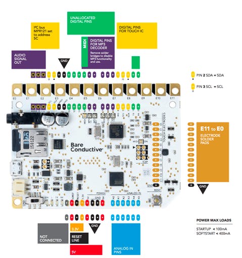
Step 4
Just connect 5v and GND to HV and GND as well as 3.3v to LV and GND on the opposite side. Then use any of the pass through pins HV1 <–> LV1, HV2<–>LV2, etc. Connect Rx and Tx (pins 10 and 11) from the touch board to HV1 and HV2, and Rx1 to LV2 and Tx1 to LV1 from the Due. 3.3v logic on the L side 5v logic on the H side.
Step 5
Double check your wiring to make sure you’ve crossed your Tx <–> Rx connections. Tx on the touch board goes to RX on the Due and vice versa.
For more detail: Paint Your Dimmer Switch on the Wall