Summary
Last several times when i buy thermometer, i saw that there is almost always difference in the values. My task was to follow the temperature and the humidity inside my baby’s room. Also there was issue reading the values from 2-3 meters range on the most thermometers and i needed to stand up to see the temp value, problem that i have with the most thermometers was the light. Other problem was I cannot see the temperature value because it is without backlight in order to save energy. I don’t want to save energy i just need a couple of hours energy storage in order this device to work if the main energy line shuts down.
So i came with an idea:
– To create thermometer with allowance to change the temperature value.
– Which can be with backlight and Colors.
– To combine all the stuffs that regular thermometers have: (RTC, Battery, Min Max t, etc)
– And to have additional features like Seasons and Holidays
So i started the project before 1 year. The software part took me several months to complete. I have created several versions of the software, and the past 2 weeks i complete the project.
Device software information
Arduino code, and libraries:
Code is also uploaded on Code step.
https://github.com/stlevkov/KT2_144
https://github.com/stlevkov/Arduino-Libraries
Device Features
- Boot Page – showing the Date and Time of the last firmware upload.
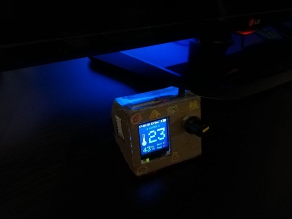
- Home Page – showing Time, Date, Battery Icon, Temperature Icon, Temperature Value, Humidity Value, Tmax, Tmin, Seasons, Holidays, USB Indicator when plugged in.
- Menu Page – with Temp, Clock, Battery, About, Back menus
- Temp Page – allows to calibrate the DHT Sensor
- Clock Page – allows to edit the Time and Date
- Battery Page – showing Battery info, % percentage, mV voltage, Charging status
- About Page – showing info for the author
- Back function for exiting the menu
- Transparent panels
- RTC long life
- Lithium battery – up to ~9 hours (450mAh)
- Low Battery indicator – showing the icon in red ~ remaining 5 min.
- Different colors for the – Low, Medium, High temperature
- Holidays and Seasons messages
- Programmable socket – at the back side
- User Interface – using Rotary Encoder
The back side with the board will not be covered, because i want by baby to see and touch the board, while the device is not powered on. You can create some kind of cover for the back side of the board.
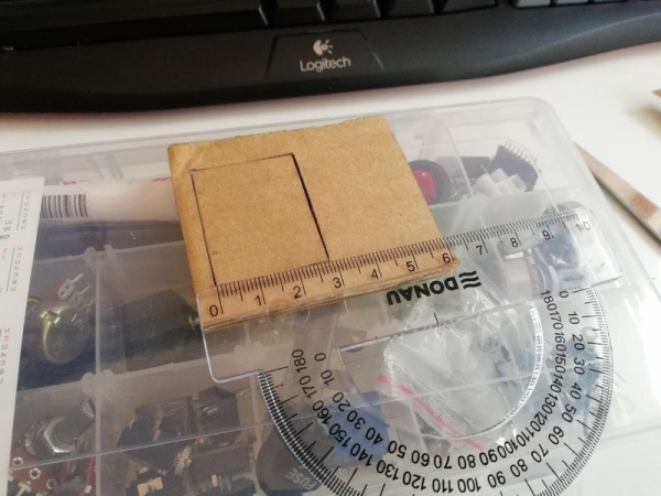
Step 1: Sketch the Device, Draw the Init Idea
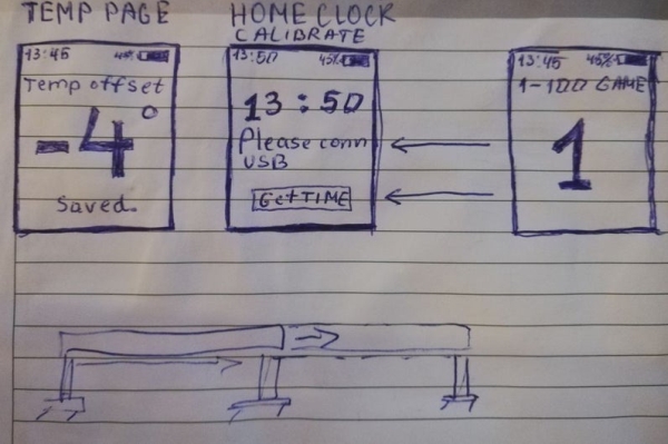
Decide what to have – how many pages, menus, how to change the menus and the pages.
If you have another ideas, you can change it with the arduino code.
Decide what form you want and what can be done easy. I first choose 3D printing, but after that decide to use simple material.
The idea is to have transparent walls on the top and on the bottom, also you can create more fine box.
So the main parts of the box are:
- Front – with the Display and Rotary Encoder
- Right – with the RTC module
- Left – with the DHT Module
- Back – with the oposite side of the board
- Top – Transparent with the 3.7V Battery and the ON/OFF Slide switch
- Bottom – Transparent
Step 2: Choose the Right Components
- TP4056 Micro USB Charger 5V 1A 18650 Lithium Battery Charging Board – Ebay
- 1.44″ 128×128 SPI Full Color 65K TFT LCD Display Module ST7735 – Ebay
- KY-040 Rotary Encoder Module for Arduino – Ebay
- DHT22 AM2302 Digital Temperature And Humidity Sensor – Ebay
- Tiny RTC I2C Modules 24C32 Memory DS1307 Real Time Clock RTC Module Board – Ebay
- Pro Micro Controller Board ATmega328P 16MHz Arduino Pro Mini Module – Ebay
- 3.7V 450mAh Lipo Rechargeable Battery – Ebay
- 6 Pins 2 Positions DPDT On/On Mini Slide Switch – Ebay
- CR2032 CR 2032 3V Button Cell Coin Battery – Ebay
- 10x22cm Soldering Prototype Copper PCB Board Single Side Universal – Ebay
- Male&Female 40pin 2.54mm Header Socket Single Row Strip – Ebay
Step 3: Prepare Wiring Diagram
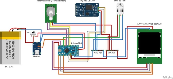
The diagram shows connectivity of the similar sensors, while the Display is almost the same.
For proper pin usage, see the Arduino code in the Code step.
Download the fritzing file for more detail about the pinout. Hover the points from the diagram to see the exact pins of the modules.
Step 4: Additional Info Before Start – Power Consumption
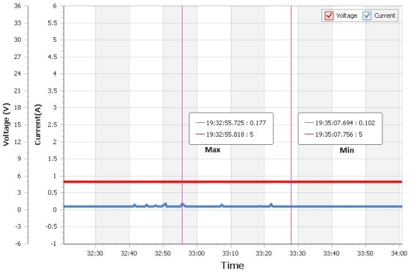
The project use 450mAh battery, but you can use greater. Just have a look at the power consumption in order to choose and calculate the right battery for specific hours usage. When using 450mAh, the device can run approx. 9 hours.
In idle the device is running with around 0.102A – No energy saving optimization are done here
When the button is pressed, the high current is applied and it is around 0.177A.
Step 5: Connect the Display
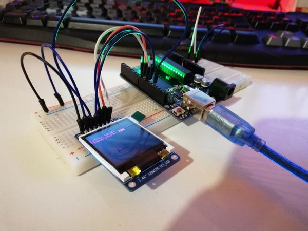
The display is using SPI for connection.
There is adafruit library for this driver ST7735.
Step 6: Connect RTC Module
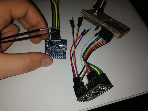
Create PCB Modification In order to use CR2032 Battery.
- Remove D1
- Remove R4
- Remove R5
- Remove R6
- Short R6
More information about this modification is found here.
Step 7: Attach Front Wall With the Display, RTC, Battery, Rotary Encoder
If you want to boot up the device, just upload the code from the Code step and follow the other steps while changing and attaching the new parts.
Source: Offline Weather Station Arduino