Some of my favorite projects are making tools that I can use with other hobbies. I am not a master woodworker by any stretch, but I do enjoy it and have created several jigs with my 3D printer that have been useful.
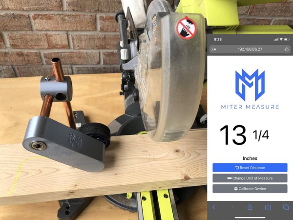
If you use a miter saw at all, you know the struggle of using a tape measure each time you want to cut a piece of wood. And making pencil marks just compounds the issue. I solved this by creating a device that will accurately measure cuts on a miter saw, every time. You will not need a tape measure or a pencil. Every cut will be exactly the length that you want it to be. I call this device the Miter Measure, and it works by measuring how far a piece of material moves along the miter saw fence and displaying the distance on a smartphone screen via a web application. Distance is measured by placing a wheel on top of the material that will rotate as the material moves underneath it. The rotation of the wheel is translated into horizontal distance and will be displayed in inches or millimeters.
The Miter Measure is easy to build and should cost less than $50. Some of the features I have added are optional, so you could reduce the cost further. It does require some 3D printed parts. If you do not have a 3D printer, I will provide some options for you below.
Step 1: Supplies
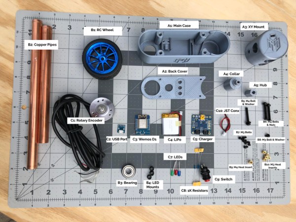
I wanted to make sure this design used supplies that were easy to source. All the supplies are available from Amazon, Adafruit or your local hardware store. Links to the products at Amazon and Adafruit are included below.
Wemos D1 – https://amzn.to/3gChdhu
Rotary Encoder – https://amzn.to/3vOFzZR
Micro USB Port – https://amzn.to/3vOFzZR
Charging board – https://amzn.to/3vOFzZR
3.7V LiPo Battery – https://amzn.to/3vOFzZR
F608ZZ Bearing – https://amzn.to/3vOFzZR
LEDs – https://amzn.to/3vOFzZR
1K Resistors – https://amzn.to/3qmI4RS
LED Collars – https://amzn.to/3qmI4RS
Switch – https://amzn.to/3qmI4RS
RC Wheel – https://amzn.to/3qmI4RS
(3) M4 Bolts 30mm
(6) M3 Bolts 6mm
(1) M3 Washer
(1) M4 Washer
(2) M4 Nuts
(1) M4 Heat Insert – https://amzn.to/3qmI4RS
(5) M3 Heat Inserts – https://amzn.to/3qmI4RS
Copper pipe – local hardware store
Wire – local hardware store
3D Printed Parts (details to follow)
Step 2: 3D Printed Parts
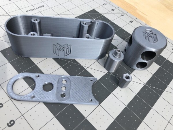
There are 5 parts that are 3D printed. I have included the STL files and STEP files. All files should be printed in the orientation that they are in. Only the collar file will need supports.
If you don’t have access to a 3D printer, there are several online services that will print files and ship them to you. Rather than list some services, here is a helpful article that lists some of these services and offers some recommendations.
11 Great Online 3D Printing Services 2021
Step 3: How It Works
It all starts with a rubber wheel from a radio-controlled car. The diameter and soft rubber made it ideal to roll easily on top of a piece of wood, or other material. The wheel is mounted to a rotary encoder. A rotary encoder measure rotation at fine increments. The rotary encoder I am using can measure 600 increments per revolution. We don’t really need that level of accuracy, but this unit is easy to work with and the size and mass help provide the weight needed to put downward pressure on the wheel. This prevents the wheel from slipping as the material runs under it.
The heart of the device is an ESP8266 board that connects everything together. I chose to use a Wemos D1 Mini board. I have had a lot of success with these boards and the smaller footprint is handy. The ESP8266 processes the data from the rotary encoder and converts it to a readable value.
All of this needs an interface, and I chose to use a web application and a smartphone instead of a built-in display. My theory here was that everyone has a smartphone and that this approach would make the hardware requirements a bit easier. My early prototypes did use OLED displays and this would be an easy addition if that is your preference.
The measurement value needs to be updated in real-time, which can be a challenge with a web application. The solution was to use WebSockets, which will send data back to the web page in real-time. I will describe this when I cover the source code.
Since the device is meant to be mounted on a miter saw, running a cord to it for power did not seem like the best approach. It is powered with a LiPo battery and features a charging board that will safely charge the battery via a micro-USB port on the back of the case.
I have added a push button latch switch and 3 LEDs to show status. All are optional if you want to reduce costs, but I would recommend at least adding the switch. Otherwise, the ESP8266 board will just run until it drains the battery.
Step 4: Wiring Diagram
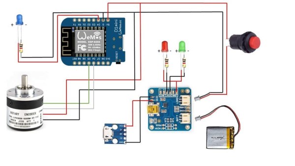
This is really two circuits. The first is the charger board, USB port and status LED. It is operable without being plugged into the Wemos board. And the Wemos board, encoder and LED can run independently of the charger circuit with a power source. Be careful of the JST connector (it comes with the Adafruit charger board). I had one that was wired in reverse and fried a board. Just double check the polarity.
As you can see from one of the photos, I used longer wires than necessary. I recommend trying to keep these shorter. It will make it easier to fit everything into the case.
Step 5: Assembly
Assembly begins with the 3D printed parts. The first step is to install the heat inserts into the main case. If you have never worked with these before, they are not hard to use. You use a soldering iron to push the insert into the plastic. The soldering iron heats the insert enough to melt the plastic and allows the insert to be pushed in. The case will have four M3 heat inserts installed.
The wheel hub mount and pipe collar also have heat inserts. The wheel mount is an M3 mount. The pipe collar uses an M4 heat insert because it needed a larger bolt. Installing the heat insert in the collar is a bit trickier. It is installed in the bottom which is inside of a cylinder.
After the heat insert is installed in the collar you can mount it on one of the copper pipes. This should be a tight fit. It may not need it, but I add a bit of super glue to ensure it stays fixed.
Now on to the wheel. The wheel mount pushes into the back of the wheel in the hex socket. The heat insert side goes in first. From the front of the wheel, attached an M3 bolt and washer through the wheel and into the hub.
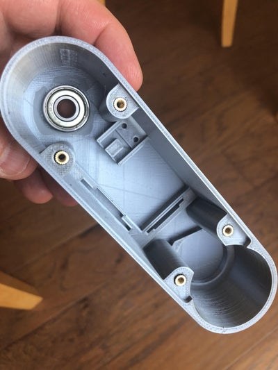
Next, we need to install the bearing in the main case. This will allow the device to easily move up and down on the saw and connects it to the mount system. This is a press fit and is probably good enough without any additional work, but I prefer to add a couple of drops of super glue to make sure it does not come loose.
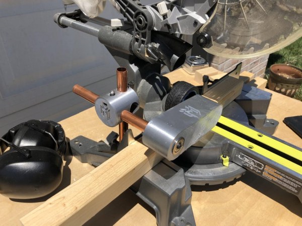
The mounting system can be setup next. The XY Mount connects a vertical and horizontal copper pipe together to create the mount system. To secure the copper pipes in place, there is a hole for an M3 bolt and a slot for an M3 nut. This mount was originally designed to use heat inserts, but I felt the pressure might be too much for them, so opted for a captured nut instead.
For now, only install the vertical pipe but make sure you have installed the nut and bolt for the horizontal pipe as well.
Step 6: Source Code
I love coding with ESP8266 devices. For this project I use the WiFi and web server capabilities to create the user interface. The basic concept is a webserver that will display the current measurement from the rotary encoder. My approach to web servers might be a little different than what you have seen. I like to embed web file contents into strings that are stored in flash memory instead of RAM. This can save a lot of RAM depending on how much web content you have.
The other interesting aspect of the code is the use of WebSockets to update the measurements in real-time. Having a web page constantly poll the ESP8266 for a new measurement would just be too slow. Rui Santos at Random Nerd Tutorials has a great article on WebSockets and ESP8266 devices. The link to his article is below. (Thanks Rui!!)
ESP8266 NodeMCU WebSocket Server: Control Outputs (Arduino IDE) | Random Nerd Tutorials
Make sure you add the WebSockets library to your project. To do this from the Arduino IDE, click Tools – Manage Libraries. Search for WebSockets and find the WebSockets for Arduino library by Markus Sattler and install it.
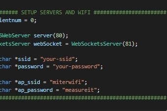
The first step before compiling and uploading the code is to provide your WiFi credentials. There are two sets of credentials. The first is for your local router and will allow the device to connect to your WiFi network and gain Internet access. Change these values to match your local WiFi settings.
The second set of credentials will specify the SSID and password for the Access Point. One problem I find when creating devices that provide a web server over the local WiFi network is determining your IP address. My answer to this was to create a WiFi Access Point that you can connect to. A pre-defined web page will display the IP address that was assigned by the router.
The Access Point credentials are for controlling access to the local Access Point. You can set these to whatever values you wish. If you leave the password blank (not recommended) then when you connect to the WiFi Access Point, you will not be asked for a password.
In theory, you could use this access point to use the device without a local WiFi network. However, I used the Bootstrap framework and decided to link to hosted files rather than embed them. You could easily code the web pages without Bootstrap and make this completely self-contained if you wanted to.
I know that most of you are going to want to customize the web page with you own look and feel. I have included the original html files and associated images so that you can modify these as you see fit. If you make changes you will need to convert these to strings which are stored as variables at the top of the file. Now, you can’t just copy code into the string. Carriage returns and quote will create a problem. And binary files, such as images, will need to be converted.
To convert files, I used a website called Tomeko.net by Tomasz Ostrowski. This is one of my favorite online tools and I can’t thank Tomasz enough for this amazing set of tools. You will need two of the tools offered here. The first is Text -> Cpp. This will convert html, css and script files to strings that can be embedded in the code.
Text – C/C++ string converter (tomeko.net)
Binary files (like images or fonts) need a different converter. The File -> Hex converter will do the job.
File to hex converter (tomeko.net)
Once you understand how the file conversion works you can modify the web files easily. The last piece of the puzzle is understanding how these files get served up by the webserver. In addition to the declared string variables, you will need to create a handler function and instruct the server what handler to call when a specific filename is requested.
Step 7: Operating Instructions

As with any battery powered project, the first thing to do is charge the battery. We will use the USB port on the back of the unit to do this. I recommend having the device powered off while charging. Plug a USB cable into the port and then into a regular USB charging source. Two of the three LEDs are charging indicators. The red LED will be lit during the charging process. When charging is complete, the red LED will turn off and the green LED will light up. I have noticed that sometimes the green LED does not stay on. (adaFruit design – not mine) If there are no LEDs lit, then your battery is charged.
To power the device on, press the push button switch. The blue LED will start blinking. It will blink while it attempts to connect to WiFi. Once the connection is established, it will turn solid and stay on to indicate that the device is powered.
If you have taken the device off of your saw to charge it, now is the time to mount it. A piece of wood should easily run under the wheel.
The user interface is a web page that can be access through your smartphone. We need to determine what IP address has been assigned to the device. If you have already figured this out from your router, then you can skip this step.
From your smartphone or tablet, connect to the WiFi network named “miterwifi”. Remember this from the source code section. If you decided to change it, then the SSID you provided is the one you need to connect to. If you have specified a password then enter it when asked. Once the connection is established, open a web browser and navigate to 10.10.10.1/wifi.htm. This page will display the IP address that has been assigned by your router.
Now you can navigate to the device user interface. The URL will be http://youripaddress/. For example, my URL is http://192.168.86.27. The web page that opens is the main screen for the device and should look as follows:
The main screen offers everything you will need to operate the device. Below the logo is the current measurement. This value will change as the wheel rotates. It can display in Inches or Millimeters.
The first thing you will need to do is calibrate the device. This will ensure accuracy based on your encoder and the wheel that is attached. You will need a ruler or tape measure for this step. There is a built-in calibration feature that is easy to use. To get started, tap the Calibrate Device button.
As per the instructions on the screen, place a board on the saw and under the wheel. We are going to measure this board as it moves 10 inches so make sure the board is long enough to do so. Once you have placed the board tap Next to continue.
Using the ruler or tape measure, move the board under the wheel and towards the saw blade – just as if you were cutting a piece of material. Move the board exactly 10 inches. If you move the board too far, you can push it backwards and the device will compensate. Once you have the board at exactly 10 inches, tap the Next button. The calibration is complete. I would recommend calibrating every time you start a new project.
The Reset Distance button is the main function. You will tap this button to reset the distance to zero. Here is how to use this. With the device mounted on your saw, push a board under the wheel along the saw fence.
With the saw off, pull the saw handle down so that the blade is low enough for the board to touch it. Then keep pushing the board under the wheel until it touches the saw blade.
Now tap the Reset Distance button. Put the saw blade back in its resting position. When the board moves under the saw blade, the distance number will reflect how far the board has moved past the blade and therefore what size the cut piece will be.
NOTE – this measure does not include the width of your saw blade. You will need to add that to get a completely accurate length.
If you are making consecutive cuts of the same length, you do not have to reset the distance. Push the board through until you get to your distance, cut, and repeat. This will give you boards that are exactly the same length every time.
And that is all there is to it. I hope you have enjoyed this Instructable as much as I have enjoyed creating the Miter Measure device. I would love to hear what you think of this project.
Step 8: OLED Update
A few of you have asked for a version with a built-in display. Good news! Here is a modified version that adds an OLED display and physical buttons to zero the distance, change the unit of measure and calibrate the device.
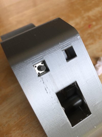
The display is a common 0.96 inch OLED display that you can buy for about $5. Adafruit has the libraries required to control the display. I have added 2 physical buttons. These are common micro switches that are available online. Note that these micro switches come in different heights. I am using the ones that have a post that is 6.5 mm high. That will allow the 3D printed button face to be installed properly.
This revised design required a new case. I made the case larger to accommodate the OLED and the buttons. There is a new back cover for this larger case as well as two buttons that are installed on top of the micro switches. The tolerances here are pretty tight so depending on your printer you may need to make some adjustments. As before, I have included STLs as well as a STEP file.
I decided to hot glue the OLED in place. The case does have a spot to mount the OLED and will be snug with a couple of dots of glue. The micro switches push into the slots and should be snug without fasteners or glue. Then the 3D printed button pieces push down on top of them and will stay in place if you give them a strong push to make sure the micro switch pin gets seated.
The circuit changes are not too difficult. The OLED needs 3.3V and ground. The SCL pin goes to D1 and the SDA pin goes to D2. For the switches, one leg of each button goes to ground. For the zero-distance switch, connect the other leg to D3. For the units/calibration button, connect the other leg to RX. I think this pretty much maxes out inputs on the Wemos board.
The code changes were not too crazy. Adafruit offers the libraries you need to control the OLED and updating the display does not take a lot of code. The buttons are also easy, but things got a little tricker with the dual-use button. One button will zero the distance. This is an often-used button, so it is dedicated to this task. The other button will change the unit of measure or manage the calibration process. Pressing the second button once will change the unit of measure. If you hold the button down for 3 seconds it will enter calibration mode.
You will need to add 3 libraries:
· Adafruit GFX Library
· Adafruit BusIO
· Adafruit SSD1306
For those who want to use the device without a WiFi connection, I have added a variable named ConnectToWifi that will control this. If you set it to 0 then the device will not attempt to connect to WiFi. This will allow you to use the device with only the OLED and physical buttons.
The operation of the device is the same as before. You can use the OLED and the web server at the same time. I would love to hear your feedback and recommendations for improvements. I already have some thoughts for the next version. I want to make the WiFi connection configurable rather than modifying the code. And I have an idea to replace the rotary encoder with a sensor from an optical mouse. This could make the “arm” piece much more compact.
Source: Miter Saw Measuring Device