Summary of Mint-Sized Success Meter (quit smoking!) with Arduino
The author created a "Quit Success Meter" to help quit smoking by combining their hobby with driving goals. This Arduino-based device tracks progress using a real-time clock and an LCD display, powered by a LiPoly battery within a mint tin. The project involves assembling components on a prototyping board before permanent installation, utilizing specific wiring for the ChronoDot RTC and Nokia 5110 LCD to ensure low power consumption and accurate timekeeping.
Parts used in the Quit Success Meter:
- Solid core hookup wire
- Standoffs and screws
- 4 pin female header
- 8 pin female header
- Two micro switches
- Solder and soldering iron
- Flush/diagonal cutter
- Wire stripper
- Multimeter
- Dremel rotary tool
- FTDI Friend or FTDI Cable
- Arduino software
- Arduino Pro Mini 3.3v
- Nokia 5110 LCD
- LiPoly battery and USB charger kit
- ChronoDot RTC
- Perma-Proto mint tin board and matching tin
panavise Junior or Helping Hands
There comes a time in life to put childish things behind and give up nasty habits. Some, like smoking, can be damn hard without constant encouragement. It was time for me to combine my favorite hobby with my driving goal and make this: The Quit Success Meter! For my other Arduino contraptions, take a look at thoughtfix.com
Step 1: Parts, Tools, and Component Preparation
The links all go to the components I used in this project.
Additional components:
Solid core hookup wire. – Radio Shack
Standoffs and screws (to mount the board in the tin. I used a kit for PC motherboards)
4 pin female header (for the ChronoDot) and 8 pin female header (for the LCD – I cut two pins off a 6 pin) – Adafruit
Two micro switches (one for system power, one for LCD power) – Radio Shack
Tools:
Solder and soldering iron – For this, having a digital station helped a lot. – Radio Shack
Flush/diagonal cutter
Wire stripper
Multimeter – Radio Shack
Dremel rotary tool or other cutting tool. I used a Dremel 4000
Panavise Junior, Helping Hands, or other tool to help soldering. – Radio Shack
FTDI Friend or FTDI Cable (to program the Arduino) – Adafruit
Arduino software.
Build everything on a prototyping board before you even touch the the Perma-Proto board. Worry about the power switches later.
First, assemble the ChronoDot, Arduino Pro Mini, and LiPoly charger according to their own instructions. Use the headers on the top of the LCD (the ones labeled 1-8, not the ones with the text labels) and use a right-angle pin line on the Arduino programming headers so they don’t stick up. There is no need to attach headers to the ChronoDot’s BAT/32K/SQW/RST pins.
Attach the LiPoly charger board’s SYS OUT + pin to the proto boards voltage line and – to the ground line. Connect the Arduino’s VCC and GND lines to the positive/negative rails on the proto board.
Step 2: Wiring
The LCD is wired just like Adafruit example code:
Proto board + rail – LCD VCC
Proto board – rail – LCD GND
Arduino pin 3 – LCD reset (RST)
Arduino pin 4 – LCD chip select (CS)
Arduino pin 5 – Data/Command select (D/C)
Arduino pin 6 – Serial data out (DIN)
Arduino pin 7 – Serial clock out (SCLK)
Proto board + rail (optional: adding a switch to this line) – LCD LED
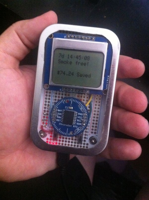
The ChronoDot uses the I2C lines: A4 and A5. On the Arduino Pro Mini, those are not attached to the standard pin lines but are broken out into adjacent pins. The photo shows the location of the lines from the under side.
Arduino A4: ChronoDot SDL
Arduino A5: ChronoDot SCL
Power line: ChronoDot VCC
Ground line: ChronoDot GND
Arduino Pro Mini 3.3v (8MHz for low power use) – Sparkfun
Nokia 5110 LCD – Adafruit or SparkFun
LiPoly battery and USB charger kit – Sparkfun
ChronoDot RTC – Adafruit
Perma-Proto mint tin board and matching tin – Adafruit
For more detail: Mint-Sized Success Meter (quit smoking!) with Arduino
- How can I combine my hobby with a driving goal?
You can build a Quit Success Meter that combines your favorite hobby with your driving goal. - What is the best way to prepare components before final assembly?
Build everything on a prototyping board before you even touch the Perma-Proto board. - Does the ChronoDot require headers on all pins?
No, there is no need to attach headers to the ChronoDot's BAT/32K/SQW/RST pins. - Can I use standard pin lines for the ChronoDot connections?
No, on the Arduino Pro Mini, the I2C lines A4 and A5 are not attached to the standard pin lines but are broken out into adjacent pins. - What type of Arduino should be used for low power use?
An Arduino Pro Mini 3.3v running at 8MHz is recommended for low power use. - How is the LCD reset pin connected?
The Arduino pin 3 connects to the LCD reset (RST) line. - Which tools are helpful for soldering?
A digital station, Panavise Junior, Helping Hands, or similar tools help with soldering. - What is the purpose of the two micro switches?
One micro switch controls system power and the other controls LCD power.