Summary of Make Your Own Arduino AC Dimmer | Drive Motors & Lights
This article details how to build a DIY Arduino AC dimmer using an ESP8266 microcontroller, capable of controlling 1200+ Watts of AC loads like motors and lights. The project integrates WiFi for home automation, featuring a custom PCB, OLED display, and 3D-printed housing. It includes comprehensive steps covering component selection, circuit design, programming, and safety warnings regarding high-voltage handling.
Parts used in the Arduino AC Dimmer:
- 10kohm Potentiometer
- 2 Double Terminal blocks
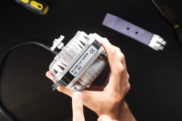
- AC motor (single phase)
- Dimmable Lightbulb
- Small 5 volts cellphone power supply
- Multimeters or clamp meters
- Micro USB SMD connector
- 1.3 inch OLED Display
- Wire
- ESP8266 Microcontroller
Hi every one, here Chris, and I want to show you how I made my own Arduino AC dimmer that can control AC loads such as motors and lights easily. It has the power to handle 1200+ Watts and It’s a very nice project for domotics and home automation because the microcontroller I used is the ESP8266 that has WiFi capabilities and the code could be adapted with few changes.
Here I leave you a tutorial with all the information so you can make your own version.If you are a visual learner I know that a video worth more than 1000 words, so here is a Tutorial video. (I am a Spanish speaker, so please consider turning on English subtitles):
Step 1: Skills Required:
This project may seem difficult or very complex, but it is definitely not completely, since you will have all the guidance for the construction, it was difficult for me to design it to make life a little easier for you. Any conceptual doubt, you are free to ask it without problems.
- You should have an understanding of:
- 3D Printing (Optional for the case).
- Arduino programming (I give you the code).
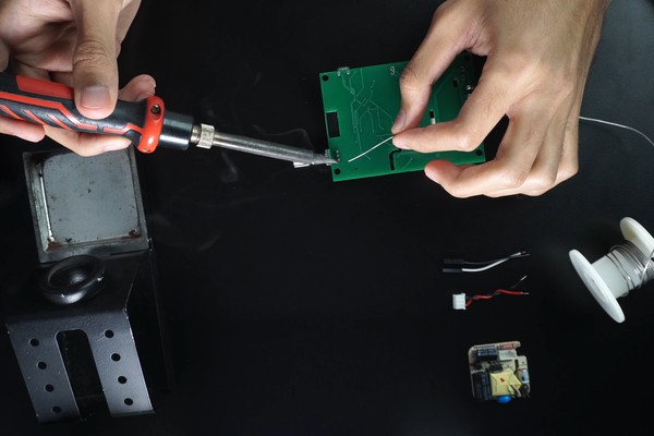
- Soldering through hole components.
Warning: In this project we will handle main power, so please be careful
Step 2: Components and Parts List
The Electronics discrete components as resistors and transistors will be attached in a BOM file in the PCB Step.
- Here is the list of what you will need for the whole process:
- -10kohm Potentiometer.
- -2 Double Terminal blocks.
- -AC motor of your preference (single phase).
- -Dimmable Lightbulb.
- -Small 5 volts cellphone power supply.
- -Measuring tools: multimeters, clamp meters (optional).
- -Micro USB SMD connector.
- -1.3 inch OLED Display.
- Wire.
BOM list of PCB components attached.
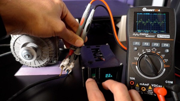
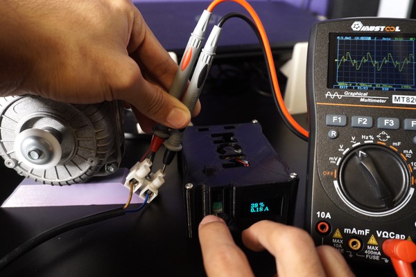
Great, cheap and awesome Graphical Multimeter to watch the Sinusoidal AC wave form
Step 3: Circuit Diagram
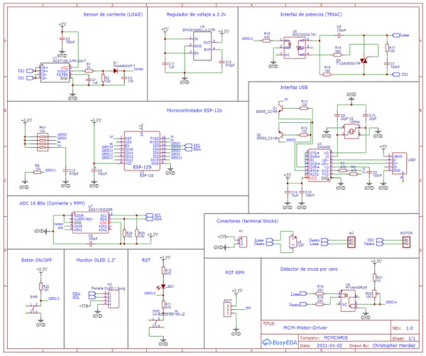
Here is the Circuit Diagram of our project:
It has all the internal conections of the circuit that will us allow to create the PCB design later.
I also attached the PDF of the Schematics so you can see it better.
Step 4: PCB Design and Ordering
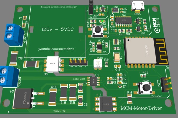
For the implementation of a good project we need a reliable assembly for the circuit that makes it up, and there is no better way to do it than with a good PCB.
Here you can download the Gerber, BOM and Pick & Place Files, the ones you need to order your PCB on your PCB manufacturing company.
I suggest JLCPCB:
$2 for 1-4 Layer PCBs⚡, Get SMT Coupons?
UnZip the .rar file with a software like WinRar or any other.
Step 5: 3D Parts (Housing + Motor Holder)
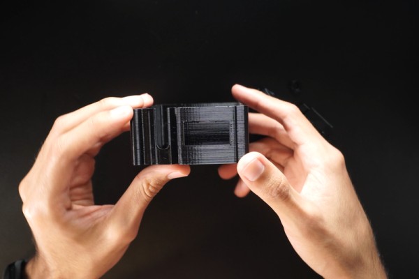
Here you have the STL files for the 3D parts of the project.
- Housing.
- Cover
- Potentiometer Knob and nut.
- Button cap.
- Motor holder.
Step 6: Programming the ESP8266 Microcontroller
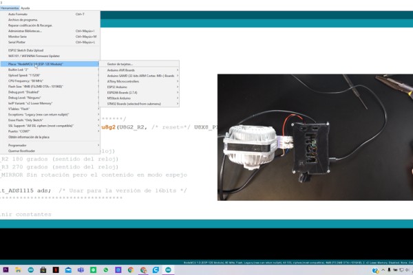
1- To program the ESP-12s we need to connect it directly to our PC through the USB cable, open the Code “ACControl”, install the libraries that I also attached and click on upload.
If the current measurements are wrong on your display, or you want to improve them, you can tune experimentally this parameters in the code:
- float Sensibilidad = 0.066; //sensitivity of the 30Amps sensor (see datasheet of ACS712 if use 20A or 5A version).
- float intercept = 35952.685; // Change this until you got closer as posible to the real current.
- float slope = 273; // Change this until you got closer as posible to the real current.
- float testFrequency = 60; // frequency of your circuit (Hz)
- float windowLength = 40.0 / testFrequency; // num of cycles that will be test.
CODE, LIBS, EVERYTHING, DOWNLOAD FOR FREE HERE
Step 7: Wiring Up
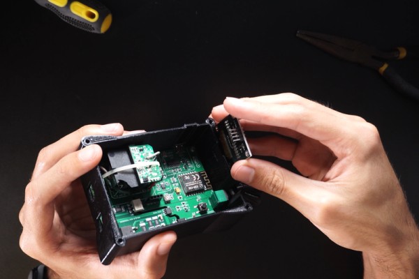
Follow this few steps carefully:
- Insert the OLED Display in the case slot.
- Wire the Display and make shure the connections are right between the PCB and OLED (Pinout may vary).
- Connect the motor or light wires (Black and Red) to the output terminal block, it doesn’t matter the polarity.
- Get an AC Cable, findout the Line and Neutral wires, and connect them respectively in the power terminal block ( INPORTANT).
Step 8: Controlling a Single Phase AC Motor
If you are in this step, you are already enjoying the successfull end of the project:
- Make shure the potentiometer is on it’s min position.
- Turn on the system.
- Click on the push button to enable the dimming function.
- Turn the potentiometer, gradually and the motor should start.
- You must see in the display the motor current.
- If you click on the push button again the motor will turn off.
Source: Make Your Own Arduino AC Dimmer | Drive Motors & Lights
- What skills are required to build this project?
You need an understanding of 3D printing (optional), Arduino programming, and soldering through-hole components. - Can this device handle high wattage loads?
Yes, the project has the power to handle over 1200 Watts. - How do I adjust current measurements if they are wrong?
You can tune parameters like Sensibilidad, intercept, and slope experimentally in the code. - Where can I download the necessary files for the PCB?
The Gerber, BOM, and Pick & Place files are available for download to order from manufacturers like JLCPCB. - Is there a visual tutorial available for this project?
Yes, a video tutorial is provided with English subtitles available for the Spanish speaker content. - How do I connect the motor or light wires?
Connect the black and red wires to the output terminal block; polarity does not matter. - What is the correct way to connect the main power input?
Find the Line and Neutral wires in an AC cable and connect them respectively to the power terminal block. - How do I enable the dimming function on the motor?
Click the push button to enable the function, then turn the potentiometer gradually until the motor starts.