Summary of Low cost Ethernet shield with ENC28J60 using Arduino
This article describes a low-cost Arduino Ethernet shield based on the Microchip ENC28J60 controller (10 Mbps), using through-hole components for easy assembly. It explains the ENC28J60 features, SPI connections to Arduino (MISO, MOSI, SCK, CS on D10, INT on D2, RESET), 25 MHz clock, voltage level shifting for 3.3V/5V logic, RJ45 with integrated magnetics and LEDs, and power from Arduino 5V and Vin with an on-board 3.3V regulator.
Parts used in the Low cost Ethernet shield with ENC28J60:
- ENC28J60 Ethernet controller (U1)
- RJ45 jack with integrated LEDs, filters and line transformers (RJ45/RJ45EM)
- 25 MHz crystal (Q1)
- Voltage regulator to generate 3.3 V (U2)
- 74HC125 buffer/level translator
- Logic level shifter (U3B) for SPI lines
- Reset microswitch (RST)
- Resistor RBIAS for LAN transceiver bias
- R11: 10 kohm resistor
- Capacitors: C1 100 nF, C10 100 nF, VCAP low ESR capacitor
- Chip holder 7+7
- Strip M/F 6 (2 pcs)
Economical alternative to original Arduino ethernet shields, allows data rates up to 10 Mbps and is achieved with a traditional assembly components.
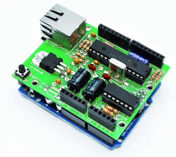
One of the most interesting shield that you can mount on the Arduino platform is certainly the ethernet shield, because enable numerous networking applications such as remote control of systems and users, web access and publication of data, and more yet, the simplicity of finding and integrating open-source libraries on Arduino IDE does the rest. The usefulness of LAN connectivity has meant that the market would respond by offering different ethernet shield, first of all the original Arduino Ethernet Shield, which was accompanied by the good shield by Seeed Studio, both of these circuits are based on the chipset WIZnet W5100, allow multiple socket connections and can work at 100 Mbps
This ethernet shield is low-cost thanks to components used: all traditional mounting (THT). This feature makes the circuit accessible to those who haven’t the equipment to assemble SMD components. The data-rate is limited to 10 Mbps.
Wiring diagram
The shield is based on a Microchip ENC28J60 chip that interfaces with Arduino and data conversion according to the ethernet protocol. It integrates the MAC controller, an 8 KB Transmit / Receive Packet Dual Port Buffer and a circular FIFO managed at the hardware level, allows the programming of data retransmission in case of collision.
The MAC controller supports both Unicast, Multicast and Broadcast packets, has a programmable 64-byte pattern within a margin allowed to the user and programmable wake-up on multiple packet formats (Magic Packet, Unicast, Multicast, Broadcast, specific packet match or any packet).
MISO is the output data of the slave device and the input of Arduino, while MOSI is the opposite; SCK is the clock that marks the two-way communication on the SPI bus and RESET the reset line, which is also connected to a button that allows you to reset the Ethernet interface, if necessary, manually. The digital D10 and D2 lines of Arduino are used, respectively, for the control of CS (Chip Select, active logic zero) and the reading of INT. U3B is used to adapt the logic levels 0/3, 3 V to those of Arduino 0/5 V.
The ENC28J60 operates with a clock of 25 MHz, defined by the quartz Q1 connected between the pins 23 and 24; the capacitor connected to pin VCAP filters the output voltage (2.5 V) of the internal controller and should preferably be of the type low ESR (low series resistance parasite). The resistor connected to RBIAS is used to bias the LAN transceiver that is part of the pin TPIN + / – and TPOUT + / -.
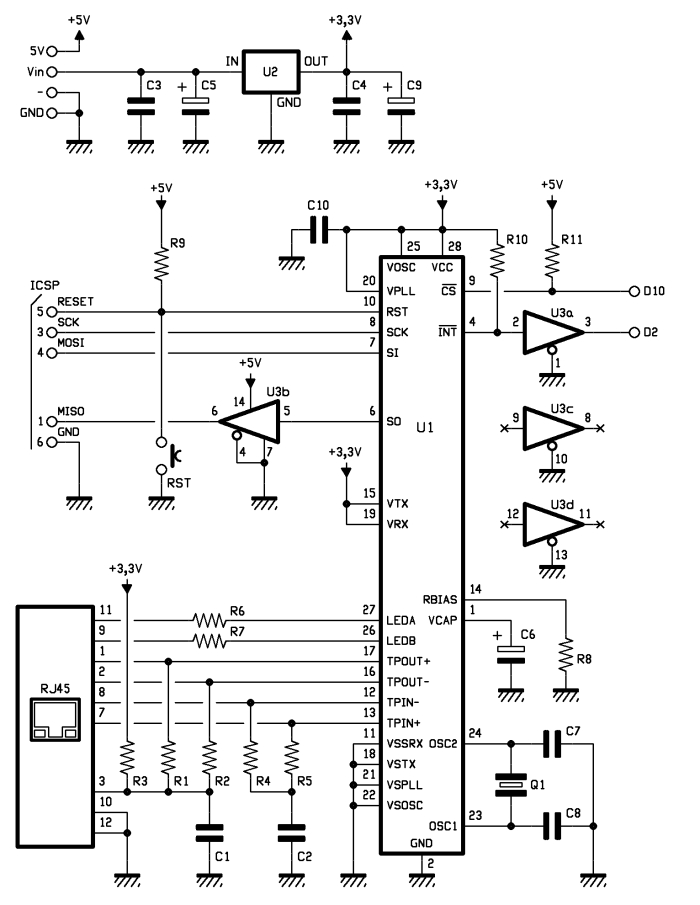
We conclude the analysis of the circuit diagram of the shield with the power that is drawn by Arduino 5V and Vin through the strip: the first provides the 5 volts continuous stabilized points of the circuit that require them (basically the 74HC125 and the resistance of pull Line-up reset and Chip Select) and the second give power to the integrated regulator U2, which creates the 3.3 volts needed to power the microcontroller and circuits contained in the RJ45 jack.
C1: 100 nF
C10: 100 nF
U1: ENC28J60
RST: Microswitch
Q1: 25 MHz
RJ45: RJ45 (RJ45EM)
– chip holder 7+7
– Strip M/F 6 (2 pz.)
For more detail: Low cost Ethernet shield with ENC28J60 using Arduino
- What Ethernet controller does this low-cost shield use?
The shield uses the Microchip ENC28J60 Ethernet controller. - What maximum data rate does the shield support?
The shield supports data rates up to 10 Mbps. - Can this shield be assembled without SMD soldering equipment?
Yes, the shield uses traditional through-hole (THT) components so it can be assembled without SMD equipment. - Which Arduino pins are used for Chip Select and Interrupt?
Digital pin D10 is used for Chip Select (CS) and D2 is used for reading the INT line. - What provides the 25 MHz clock for the ENC28J60?
The 25 MHz clock is provided by a 25 MHz crystal connected between pins 23 and 24 of the ENC28J60. - How is 3.3 V power supplied to the ENC28J60?
Vin powers an onboard regulator (U2) that creates the 3.3 V needed to power the ENC28J60 and RJ45 circuitry. - Does the shield include a reset option for the Ethernet interface?
Yes, a RESET line is connected to a microswitch that allows manual reset of the Ethernet interface. - What SPI signals connect the ENC28J60 to Arduino?
The SPI signals are MISO (slave output), MOSI (slave input), SCK (clock), and CS (Chip Select). - Are there components to adapt logic levels between 3.3 V and 5 V?
Yes, a voltage level shifter (U3B) and buffers like the 74HC125 are used to adapt logic levels between 3.3 V and 5 V.