Summary of LED Head Arduino TED
Debug TED is a creative breadboard companion designed as a crude voltage meter and serial communication indicator. Built around a bare-bones Arduino 328p, it uses a vertical LED bar to display voltage levels from 1V to 5V while its "eyes" flash during data transmission. The project repurposes simple components into a functional debugging tool that visually confirms power stability and serial activity on a breadboard.
Parts used in Debug TED:
- Arduino 328p
- Voltage divider
- 5 LEDs (1 Red, 2 Amber, 2 Green)
- 2 SMD LEDs (608 size)
- 3 Resistors (220ohm)
- 1 Resistor (1kohm)
- 1 Resistor (2.2kohm)
- Hobbywire
- Atmel 328p Chip
- Arduino UNO
- AVR MKii programmer
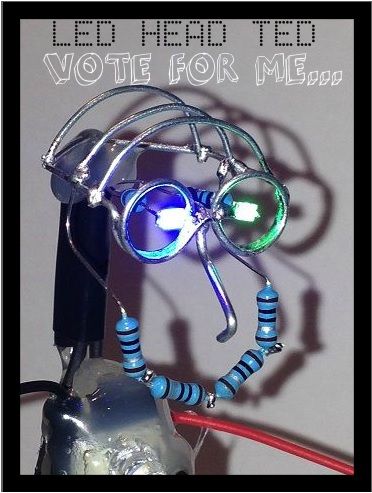
LED HEAD TED meet the world.
I have always been interested in a bare-bones Arduino but never really saw the point if it was not practically useful, This is my entry into Little Bits contest, I tried to stay true to the ” little bits” theme and use…well little bits that I had lying around the house. So I introduce to you my bread board companion called Debug TED.
Here is a short video of him in action, when you start the board up the leds run in order from bottum to up to show they all working and when code is loaded onto the board the eyes flash( connected them to TX0 and RX0)
once they where up and running i connected his probe to the 5v line and he indicated that it was in the 4volt range (actual reading 4.6v) and when connected to 3.3v (after accidentally connecting to Gnd) he shows LED3 indicating the 3volt range.
He is made up of a barebones
x1 Arduino 328p ,
x1 Voltage divider,
x5 LEDs
x2 SMD LEDs
x3 220ohm Resistors
x1 1kohm Resistor
x1 2.2kohm Resistor
His function
He is a breadboard hardware debug tool , made to be used as a very crude voltage meter, the output of the measured voltage is displayed on his tummy from bottom to top in steps of 1v steps all the way to 5v.
His eyes is two SMD leds with leads that “T” joins and serial communication and flicker when serial communication is active.
His legs is the main power feed into his body and needs to be supplied with 5v to power him up.
His Glasses and head is the negative to the system and all other negatives is connected to the skull for a GND.
His arms indicated by RED and Black leads is the Volt meter probes for testing voltages in the circuit being built.
The only non functioning part about TED is his smile which he was missing badly 😉
Hope you guys like Him if you do and want to see more please vote! I am planning on making him into a kit with more features !
Tutorial guideline to follow, please take note that this is not clear cut tutorial as everyone will have there own why of doing things but i will explain with Lots of photos.
Step 1: Building the light bar
The light bar is made up of 5 LEDs
x1 RED
x2 Amber
x2 Green
To give the light bar some strength I ended up using hobbywire to connect all the negatives together which would later be connected through a common 220ohm resistor to ground ( 220ohm is enough because one one led will be switched on at a time) and on the positive lead i soldered different color wires. from top to bottom they were soldered in the following order.
Green = 5v
Green = 4v
Amber = 3v
Amber = 2v
Red = 1v
But this is open to your judgement and choice.
Step 2: Creating the eyes (TX and RX indicators)
The eyes is two green and blue SMD 608size LEDs connected to 220ohm resistors, the glasses was made form hobby wire and soldered to the common negative rail between the two LEDs for a negative feed. the other ends is soldered to two jump wires for use to connect to the bread board TX and RX lines ( not that the face does not integrate into the on board Arduino)
Step 3: Burning the bootloader and loading the code
What you need.
Hardware
Atmel 328p Chip
Arduino UNO
AVR MKii programmer
Software
Atmel Studio
Arduino IDE
This is one of the only project you will probably ever find that you load the code first ! then build the project, This is because i never plan to reuse, reprogram this chip as it is used as a tool.
Read more: LED Head Arduino TED
- How does the Debug TED indicate working LEDs?
When the board starts up, the LEDs run in order from bottom to top to show they are all working. - What do the eyes of Debug TED represent?
The eyes consist of two SMD LEDs connected to TX0 and RX0 lines that flash when serial communication is active. - How does the device measure voltage?
It functions as a crude voltage meter where the output is displayed on the tummy in 1v steps ranging from 1v to 5v. - What voltage range did the probe indicate for the 5v line?
When connected to the 5v line, the probe indicated a reading in the 4 volt range with an actual measurement of 4.6v. - Which LED lights up when measuring 3.3v?
When connected to 3.3v, LED3 lights up to indicate the 3 volt range. - How are the eyes connected to the circuit?
The eyes are connected via jump wires soldered to hobby wire glasses to the bread board TX and RX lines. - What is the power requirement for the Debug TED legs?
The legs serve as the main power feed and need to be supplied with 5v to power up the unit. - Why is the bootloader burned before building the project?
The code is loaded first because the chip is intended to be a dedicated tool rather than being reused or reprogrammed later.