
Summary of LED Control Using Touch Button
This project demonstrates controlling an LED on the 4Duino's D13 pin using a resistive touch button widget via the 4D Workshops interface. It explains LED polarity, the role of current-limiting resistors, and how to identify anode/cathode leads. Since the 4Duino has an internal LED connected to D13, no external circuit building is needed; only the Micro USB cable is required for programming using Workshop 4 or the Arduino IDE.
Parts used in the 4Duino LED Control Project:
- 4Duino device
- Micro USB cable
- Internal LED (connected to I/O pin D13)
- 4D Workshops software environment
- Arduino IDE (for compilation support)
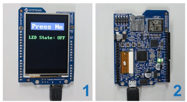
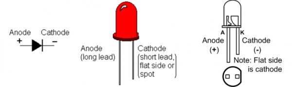
In this project, we will learn how to turn an LED ON or OFF via the 4Duino I/O port (D13) and a button widget from 4D Workshops. The 4Duino’s resistive touch display is used as a means for a graphical interface to control state of the LED. For convenience, we will use the LED on pin D13 of the 4Duino to conduct this project. An LED (light emitting diode) works on the basic principle that when potential difference is applied across the anode and cathode, light is emitted. The higher the potential difference, the brighter the LED shines. LEDs being diodes have polarity and will only work if current flows from the anode to the cathode, therefore positive must always be connected to the anode and ground to the cathode. The longer lead of the LED is the anode whilst the shorter lead is the cathode. A resistor is typically placed before the anode in order to lower the current flowing through the LED. This will extend the lifespan of the LED and dim the brightness to a level that is more comfortable to look at.
Note: If you end up clipping the leads, the anode lead can be found by looking inside the LED and examining the metal contacts – the larger contact is the cathode. The plastic casing of the LED can be used to determine polarity on the LED as well – the side of the cathode will have a flat edge.
HOW IT WORKS
COMPONENTS
This projects utilizes the internal circuitry of the 4Duino, hence no external components is required for this project. However, you will require a Micro USB cable to program the 4Duino.
IMPLEMENTATION
Step 1: Build
4Duino has an inbuilt LED connected to the I/O pin D13. Circuit building is not required at this stage.
Step 2: Program
Workshop 4 – 4Duino Basic Graphics environment is used to program this project. (The same could be implemented in the latest Arduino IDE)
This project requires the Arduino IDE to be installed as Workshop calls the Arduino IDE for compiling the Arduino sketches. The Arduino IDE however is not required to be opened or modified to program the 4Duino.
Read more: LED Control Using Touch Button
- How do you control the LED state in this project?
You control the LED ON or OFF state via the 4Duino I/O port D13 using a button widget from 4D Workshops. - What component is used as the graphical interface?
The 4Duino's resistive touch display serves as the graphical interface to control the LED state. - Is external circuit building required for this project?
No, the project utilizes the internal circuitry of the 4Duino where an inbuilt LED is already connected to pin D13. - Which software is used to program this project?
Workshop 4 – 4Duino Basic Graphics environment is used, which can also be implemented in the latest Arduino IDE. - Do you need to open the Arduino IDE directly?
No, the Arduino IDE is not required to be opened or modified since Workshop calls it for compiling sketches. - How can you identify the cathode lead if clipped?
If leads are clipped, look inside the LED; the larger metal contact indicates the cathode, and the plastic casing will have a flat edge on that side. - Why is a resistor typically placed before the anode?
A resistor lowers the current flowing through the LED to extend its lifespan and dim the brightness to a comfortable level. - What happens when potential difference is applied across an LED?
Light is emitted, with higher potential differences causing the LED to shine brighter.
