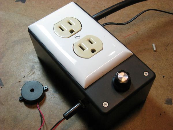
The Knock Box is a power strip with superpowers – it turns on your lamp whenever you knock on your nightstand. You get two outlets, individually controlled by knock-knock-knocking on a nearby hard surface. It’s great for hitting the lights when it’s pitch dark, but if an appliance can plug into the wall, you can toggle it!
Control your lamp, turn on your fan, kill your alarm clock, or start the music in style, using any flat surface as your lightswitch.
I was inspired to build the Knock Box when I woke up one night, stubbed my toe on my dresser, then knocked my lamp onto the floor as I reached for the fan. Now I can control both, independently, from my bed, in pitch darkness, no switches required. And so can you! SCIENCE!
What’s better: You can build a Knock Box over a weekend, and all of the electronics can be bought at any Radio Shack. Just add a few bucks of electrical gear from the hardware store and you’re ready to, a-hem, knock this one out.
IMPORTANT WARNINGS!
– If you’ve never worked off a schematic before, this project will be difficult. Try building it on a breadboard first.
– This project involves mains voltage, which could start a fire or kill you. Think things through and be careful.
Step 1: Equip Yourself!
If you don’t recognize a term in the parts list, ask a Radio Shack guy. He’ll either help you out, or his head will explode in confusion. Either way, good times.
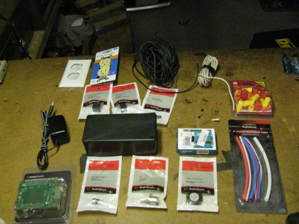
Radio Shack Shopping List:
– A 12V “Wall Wart” power supply, at least 500mA, center positive 2.1mm jack. A salvaged one works too.
– An Arduino Protoshield. Seeedstudio’s protoshield is actually great here, since it has a small bank of 14-gauge wire holes.
– Two relays, at least SPDT, rated 10A@120VAC or higher, 12V coil current
– A large project box, 3″x6″x2″, made of plastic.
– A 2.1mm power plug, panel mount
– A 2.1mm power jack. Mine came two in a bag. Bonus!
– A 10kΩ potentiometer, panel-mount
– Two 1kΩ resistors
– One 1MΩ resistor
– Two 2N2222 transistors or other transistor capable of switching 200mA
– Two 1N4001 diodes or other snubbers
– An Arduino Uno, for street cred
– A piezo element. Careful – this is not a piezo buzzer! The package will remind you to drive it with a square wave, that’s your man.
– Heatshrink. We love heatshrink!
– Not shown: 22 AWG wire, stranded and solid, multiple colors
– Not shown: Electrical tape
– Not shown: Potentiometer knob
Home Depot Shopping List:
– An outlet cover
– An outlet. Mine has particularly pretentious packaging that claimed it was a “Duplex Receptacle.”
– Black and white 16-gauge wire. Solid is preferred, but stranded is easier to cram into the case. I used stranded. You can salvage this from extension cords.
– Wire nuts
– Not shown: A three-pronged plug with wire. You can salvage an old cord, or buy a cheap extension cord to cut apart.
– Not shown: Two 1/2″ long bolts, 1/4″ or smaller, with nuts.
– Not shown: Electrical tape
Tools:
– Soldering gear
– Flush cutters, stripper, etc
– Dremel with drills, cutoff wheels, etc
– Scriber or pencil
– Heat gun or lighter
Step 2: Build the Shield
Might as well upload the code first. It’s attached. You know what to do!
The schematic for the protoshield is at left. Build it! It’s a tight fit with the big relays, so use my pictures as reference.
The set of red, yellow, and black wires are 8″ long. The set of red and black wires are 36″ long.
CRITICAL, NON-OBVIOUS STEP! Due to hilariously bad design mistakes on the Seeedstudio protoshield, you must solder in the ICSP headers for this to work. Solder in all the headers, including the ICSP headers, FIRST, before adding other components. I made this mistake, so some of my pictures don’t have them.
Relay Tip: The pins aren’t on a 0.1″ grid, so you will need to force the relay onto the board. SOLDER THE ICSP HEADER BEFORE THE RELAYS. Experts: You may want to cut off the NC pin to make your life easier.
Detailed soldering instructions:
0) Watch a YouTube video on how to solder things to a perfboard.
1) Solder the pin headers and ISP headers. Test-fit the protoshield onto the Arduino.
2) Check out the back of the relay’s package. You’ll notice that two pins are connected by a coil, and three go with the switch. The switch is by default connected to one pin – this one is called NC. When activated, it snaps to the other pin – that one is called NO.
3) Jam the relays onto the board, exactly like in the picture, hard. Make sure all the pins make it through to the other side. Solder them in place using extra, extra-large blobs of solder.
4) Insert the 1N4004 diodes into the board. Each diode’s pins should be right next to the respective relay’s coil pins. Each diode has one white band – these must face away from each other. Solder them in place and bridge them onto the coil pins. Trim the leads.
5) Insert the 2N2222 transistors into the board according to the picture. Note that they’re facing opposite directions. To clarify, hold the transistor with the legs down and the flat side towards you. The left pin of each must be next to the diode pin without the white stripe. The right legs of each must be next to each other. The middle legs must be in their own rows. Solder the transistors into place, bridge the left legs onto the diodes, and bridge the right legs together. Trim the legs.
6) Insert one leg of one 1kΩ resistor adjacent to the middle leg of one transistor. Insert the other leg into Pin 4 labelled on the shield. Solder the resistor, bridge the leg to the transistor, and trim the leads. Repeat with the other resistor, going from the middle leg of the other transistor to Pin 5.
7) Solder the 1MΩ diode so it bridges two rows of the little prototyping area in the bottom-right. Trim the leads.
8) Solder in a short wire to any hole in the same shiny row as the resistor. The other side goes to the nearby hole labeled GND.
9) Solder another short wire to any hole in the same row as the other side of the resistor. Solder the other side into the hole labeled SCL. Fun fact: SCL is Pin A5 on the Arduino.
10) Find two holes, each next to the stripe side of a diode. Solder a wire between them and bridge them to the diodes.
11) Find another hole next to the stripe side of one diode. Solder a wire in there and bridge it to the diode. Solder the other side to the hole labeled VIN.
12) Remember when you soldered the legs of the transistors to each other? Find a hole adjacent to those legs and solder a wire in there. Solder the other side to a hole labeled GND.
13) Solder a wire near the NO pin of a relay and bridge them. Find the area with especially large holes. See how each big hole has a small hole next to it? Solder the other end to the leftmost small hole, being careful not to block a big hole. Do not trim this wire after soldering.
14) Solder a wire near the input of that same relay. Bridge it to the input. Solder the other end to the next small hole in the area with the big hole. Do not trim this wire after soldering.
15) Repeat Steps 13 and 14 for the other relay.
16) Strip a red, a black, and a yellow wire, 8″ long each. The colors are important. Solder the red to a hole labeled VCC, the black to a hole labeled GND, and the yellow to a hole labeled A3.
17) Strip a red and a black wire, 36″ long each. Again, colors are important. Solder the red in the same row as the row you connected to SCL, and the black to the other row that you connected to GND.
18) You’re done with the relay shield!
Step 3: Add the Plug and Knob
Cut five pieces of 1/4″ heatshrink, about an inch long each, and thread one onto each wire dangling off your shield.
First up, the wires connected to that 1MΩ resistor. Grab your 2.1mm plug and solder the red wire onto the center post tab. Solder the black wire onto the barrel tab. Be careful not to solder it to the detector tab by accident. Slip down the heatshrink and shrink it.
Grab that 10kΩ pot. With its knob facing you, solder in the wires – black, yellow, then red. Slip down the heatshrink and shrink it.
Step 4: My Big Fat Grey Wires
We’re going to solder very large wires in this step. You may need to turn up the heat on your iron, and be extra-patient, while soldering. This copper can absorb a lot of heat!
Cut four pieces of white 16-gauge wire, about 8″ long. Strip one side to about 1/2″. Twist the copper and tin one side (apply solder directly to the wire).
Push the tinned wires through the big holes and solder them in place. Bridge each with its respective 22-gauge wire. Really blob on the solder to ensure rock-solid joints. Cut the wires as flush as possible.
Strip about 3/4″ of insulation from the wires. Twist the copper but do not tin it.
Use a knife or coax cutter to remove about 3″ of sheathing from the power cord, exposing the three wires within. Strip about 3/4″ of insulation from each. Twist the copper but don’t tin it.
For more detail: The Knock Box: Build a Knock-Sensitive Power Strip


