Summary of Keyless Entry / Arduino
This article details a DIY Keyless Entry System using an Arduino-based microcontroller. The system features a 3x4 matrix keypad for code entry, a servo motor to unlock the door, and visual feedback via LEDs (green for success, red for failure). It includes a helper light that activates on key press, a manual override switch for power outages, and is powered by a wall charger with voltage regulation components.
Parts used in the Keyless Entry System:
- Atmega328P-UP Bootloaded
- 28 Pin socket
- 16Mhz Crystal
- 22pF caps ( 2 )
- LM317 voltage regulator
- LM7805 Voltage regulator
- 10uF Caps ( 2 )
- #104 Caps ( 2 )
- 220R Resistor
- 1K Resistor
- 470R Resistor
- 10K Resistor
- LED of your choice
- Tact Switch
- 5mm Power Connector
- 2 pin female header
- 16 Pin Female header
- Perf Board 70mm x 90mm
- Flat wire strips 2 wire 4 wire 7 wire 1' long
- Servo
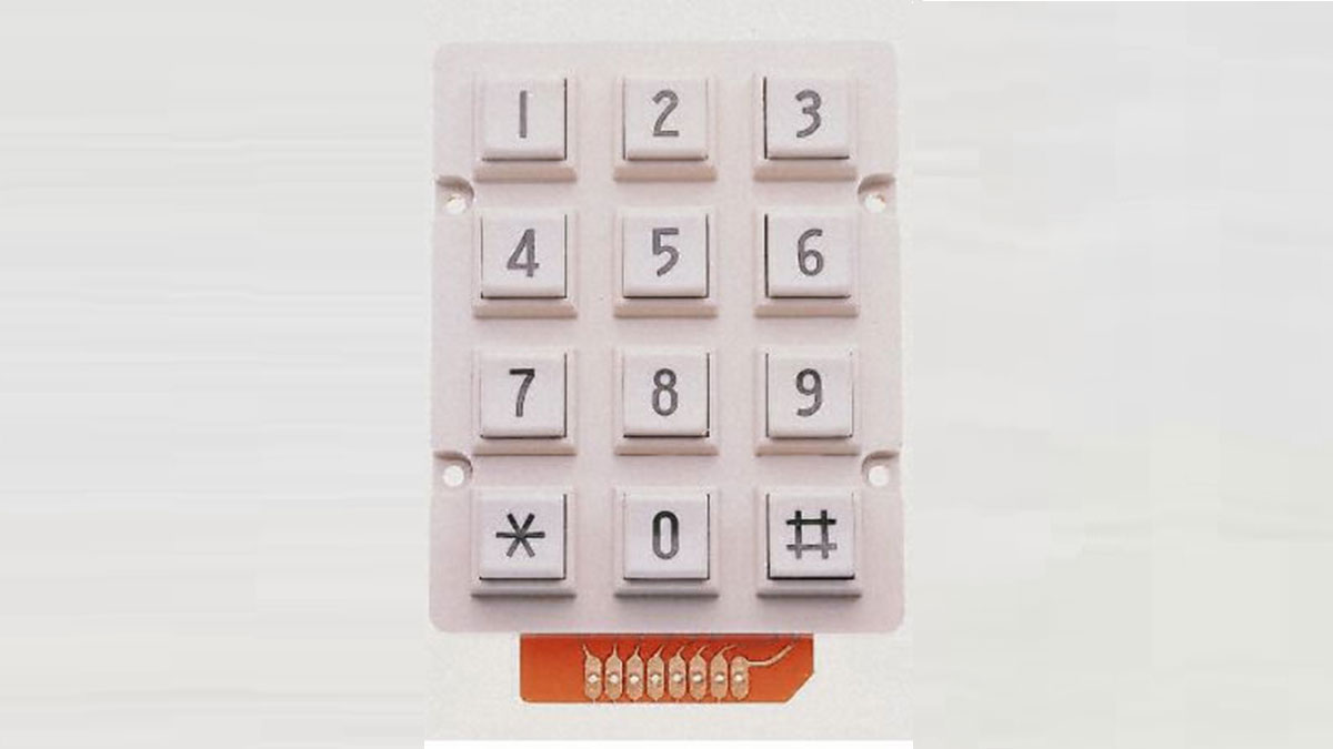
Keyless Entry System
Enter the correct code into the keypad and the servo will unlock the door. Enter the incorrect code and Sorry you stay out.
There was a couple of stipulations i wanted in my Keyless Entry system:
- Helper Light. A light that would come on whenever a key was pressed. Then off after the preset time limit.
- An override switch so the servo could be operated without the keypad.
- Some indication that the pass code entered was correct or not.
- Powered by a wall charger.
- Be able to operate manually during a power outage
With these stipulations i started out to build.
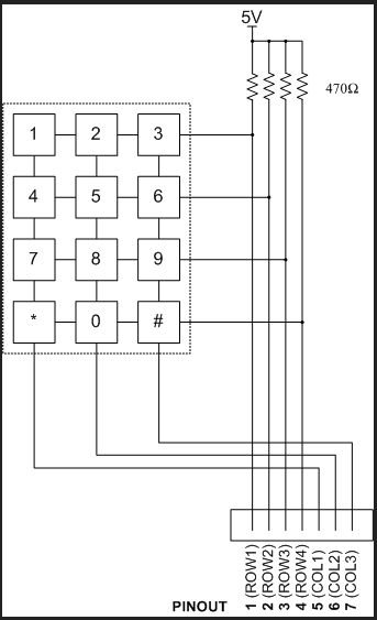
The Keypad works on a matrix system. Pressing any key will involve 2 wires.
Example if you press number 8 it will effect the wire ROW3 and CLO2. By this the micro controller can determine what key was pressed with only 7 wires from the keypad.
While this keypad schematic is not correct to this build the theory is still the same.
This build does not use the external resistors. It takes advantage of the internal pullup resistors in the Atmega328.
The Circuit
I couldn’t find a Keypad in Fritzing so i used 3 mystery parts where it says KEYPAD in the diagram.
Its probably better to use a pullup resistor on the switch instead of a pull down, but either way will work.
Code
I had some help from maewert for the Helper Light.
The Bypass switch the hardest for me. It was a collaboration between sath02 and my self. I am always greatful to these guys for there knowledge.
If you don’t have the libraries needed for the sketch they are here for downloading.
Reference
#include <Password.h>
#include <Keypad.h>
#include <Servo.h> //tells to use servo library
int pos = 5; // variable to store the servo position
int button = A0; // The button will be on Pin 7
Servo myservo; //declares servo
#define DELAY 20 // Delay per loop in ms
Password password = Password( “4444” ); //password to unlock door, can be changed
const byte ROWS = 4; // Four rows
const byte COLS = 3; // columns
// Define the Keymap
char keys[ROWS][COLS] = {
{‘1′,’2′,’3’,},
{‘4′,’5′,’6’,},
{‘7′,’8′,’9’,},
{‘*’,’0′,’#’,},
};
byte rowPins[ROWS] = { 5, 4, 3, 2 };// Connect keypad ROW0, ROW1, ROW2 and ROW3 to these Arduino pins.
byte colPins[COLS] = { 8, 7, 6,};// Connect keypad COL0, COL1 and COL2 to these Arduino pins.
// Create the Keypad
Keypad keypad = Keypad( makeKeymap(keys), rowPins, colPins, ROWS, COLS );
unsigned long offtime;
boolean helper_light_is_on = false; // helper light off
// variables will change:
int buttonState = 0; // variable for reading the pushbutton status
int lastButtonState = 0;
void handle_button()
{
// read the state of the pushbutton value:
buttonState = digitalRead(button);
// check if the pushbutton is pressed.
if (buttonState != lastButtonState) {
// Lock release
myservo.write(100);
delay(20);
digitalWrite(10, HIGH);
delay(1000); // this delay could be changed to suitable value
digitalWrite(10, LOW);
myservo.write(160);// move to lock position after 5 second
delay(20);
}
lastButtonState = buttonState;
}
void setup()
{
Serial.begin(9600);
Serial.write(254);
Serial.write(0x01);
delay(200);
pinMode(10, OUTPUT); //Helper light
pinMode(11, OUTPUT); //green light
pinMode(12, OUTPUT); //red light
pinMode(button, INPUT);
myservo.attach(9); //servo on digital pin 9 //servo
keypad.addEventListener(keypadEvent); //add an event listener for this keypad
pinMode(pos, OUTPUT);
pinMode(button, INPUT);
delay(200);
}
void loop()
{
handle_button();
keypad.getKey();
myservo.write(5);
process_helper_light();
}
//take care of some special events
void keypadEvent(KeypadEvent eKey)
{
switch (keypad.getState())
{
case PRESSED:
// a key is pressed so light the helper light
helper_light_is_on = true;
digitalWrite(10,HIGH);
offtime = millis() + 10000; // set the offtime for 30 seconds in the future
Serial.print(” enter: “);
Serial.println(eKey);
delay(10);
Serial.write(254);
switch (eKey)
{
case ‘*’:
checkPassword();
delay(1);
break;
case ‘#’:
password.reset();
delay(1);
break;
default:
password.append(eKey);
delay(1);
}
}
}
void checkPassword()
{
if (password.evaluate()) //if password is right unlock door
{
Serial.println(” Accepted”);
Serial.write(254);
delay(10);
//Add code to run if it works
myservo.write(90); //160deg
digitalWrite(11, HIGH);//turn on Green Led
delay(3000); //wait 5 seconds
digitalWrite(11, LOW);// turn off Green Led
}
else
{
Serial.println(” Denied”); //if passwords wrong keep door locked
Serial.write(254);
delay(10);
//add code to run if it did not work
myservo.write(5);
digitalWrite(12, HIGH); //turn on RedLed
delay(3000); //wait 5 seconds
digitalWrite(12, LOW);//turn off Red Led
}
{
if (digitalRead(button) == LOW)
myservo.write(90);
//for(pos = 0; pos < 90; pos += 90) // goes from 0 degrees to 90 degrees
{ // in steps of degree
Serial.println(” Opened “);
myservo.write(pos);
myservo.write(90); //160deg
//delay(80);
myservo.write(pos); // tell servo to go to position in variable ‘pos’
}
if (digitalRead(button) == HIGH)
//else
//for(pos = 90; pos>=90; pos-=90) // goes from 90 degrees to 0 degrees
myservo.write(90);
{
Serial.println(” Stay Closed “);
myservo.write(pos); // tell servo to go to position in variable ‘pos’
delay(50);
myservo.write(5); //160deg
myservo.write(pos); // tell servo to go to position in variable ‘pos’
}
}
}
// this routine turns off the light when the timer expires
void process_helper_light(void)
{
if (helper_light_is_on)
{
if (millis() >= offtime)
{
digitalWrite(10,LOW); //turn off the helper light
helper_light_is_on = false;
}
}
}
 Keypad.rar16 KBServo.rar7 KBPassword.rar5 KB
- Atmega328P-UP Bootloaded
- 28 Pin socket
- 16Mhz Crystal
- 22pF caps ( 2 )
- LM317 voltage regulator
- LM7805 Voltage regulator
- 10uF Caps ( 2 )
- #104 Caps ( 2 )
- 220R Resistor
- 1K Resistor
- 470R Resistor
- 10K Resistor
- LED of your choice
- Tact Switch
- 5mm Power Connector
- 2 pin female header
- 16 Pin Female header
- Perf Board 70mm x 90mm
- Flat wire strips 2 wire 4 wire 7 wire 1′ long
- Servo
For more detail: Keyless Entry / Arduino
- How does the keypad determine which key was pressed?
Pressing any key involves two wires, allowing the microcontroller to identify the specific key using only seven wires from the keypad. - Can the system be operated manually during a power outage?
Yes, the project includes an override switch so the servo can be operated without the keypad or external power. - What happens if the pass code entered is incorrect?
The system displays a red LED, keeps the door locked, and prints Denied to the serial monitor. - Does the helper light stay on indefinitely?
No, the helper light turns off after a preset time limit of 10 seconds once a key is pressed. - What is the default password for this system?
The default password set in the code is 4444. - How does the system indicate a correct pass code?
It turns on a green LED and moves the servo to the unlocked position. - Are external resistors used for the keypad circuit?
No, the build takes advantage of the internal pullup resistors in the Atmega328 chip. - What pins are used for the servo motor?
The servo is attached to digital pin 9.