Summary of From Arduino to Atmega32: A Programmer’s Journey with ISP
This article details how to transform an Arduino UNO into an In-System Programmer (ISP) to program an Atmega32 microcontroller, bypassing the need for expensive dedicated programmers. It covers hardware assembly, necessary software configuration within the Arduino IDE, and provides a complete C code example to blink an LED on the Atmega32 chip.
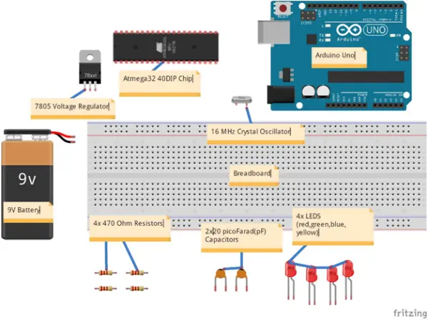
Parts used in the Arduino as ISP Project:
- Arduino UNO
- Atmega32 Chip
- 16MHz Crystal Oscillator (Optional)
- 2x 20picoFarad Capacitors (Optional)
- Breadboard
- 4x Light Emitting Diodes (LEDs)
- 4x 470 Ohm Resistors
- Arduino IDE
- 9V Battery & 7805 Voltage Regulator (Optional)
- Male-Male Jumper Cables
A discourse of “embedded systems”
Whether you are cognizant of it or choose to overlook this undeniable fact, you are either in possession of or have utilized an electronic device. This could range from a phone, an ATM machine, a radio, a laptop computer, a gaming console, a smart TV, a smart card reader at the supermarket, or a microwave oven, among others. What ties them all together is the presence of a computer within their confines. The size of this computer is so diminutive in comparison to its housing that it has been aptly termed “embedded” by technocrats. Given that this embedded computer facilitates input, processing, and output, it is fittingly recognized as an “embedded system.”
Embedded systems manifest in various forms, such as Programmable Logic Devices (PLDs), microcontrollers, and more. Pertinent to our discussion today, certain embedded systems come preprogrammed to perform specific functionalities before integration into a complete system. In contrast, others arrive as bare chips, awaiting programming and reprogramming at your discretion. The latter category particularly highlights In-System Programming (ISP) characteristics, with a focus on microcontrollers.
Why Arduino
Requirements
1. Arduino UNO
2. Atmega32 Chip
3. 1x 16MHz Crystal Oscillator (Optional)
4. 2x 20picoFarad Capacitors (Optional)
5. Breadboard
6. 4x Light Emitting Diodes (LEDs)
7. 4x 470 Ohm Resistors
8. Arduino IDE
9. 9V Battery & 7805 Voltage Regulator (Optional)
10. Male-Male Jumper Cables
11. Ensure you have downloaded and installed the Arduino IDE.
Hardware Setup
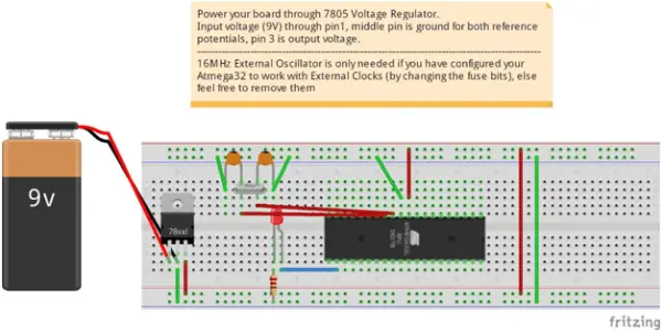
Establish the circuit according to the provided instructions and diagram. It’s optional to exclude the crystal oscillator-capacitors part, as its relevance will be explained in the “uploading code section.”
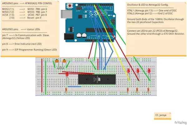
The 5V power and ground connections for Atmega32 are established through Pins 10 and 11, respectively. The LED array on the right serves as an indicator for the proper functioning of Arduino as an ISP. These LEDs will blink according to the communication status, with more details to be discussed later. The blue-wired connections facilitate code uploading to the microcontroller, while the remaining circuitry consists of the essential working components of the microcontroller. Make sure your Arduino is properly connected to your computer.
Software setup
This segment plays a crucial role in configuring the circuitry. It facilitates the interaction between your computer software and the Atmega hardware. It can be rightfully considered the core of your circuitry, as it communicates with the device drivers in your Atmega32 to execute your code. Therefore, navigate this terrain with care, as the process typically takes around two minutes.
1. Begin by downloading the compressed file (2.61MB) and extracting it to your desktop. The file includes the Atmega32 Datasheet, boards.txt file, pins_arduino c header file, and HardwareSerial C++ header file.
2. Proceed to add Core Board definitions. This step allows your Integrated Development Environment (IDE) to compile programs specifically targeting your Atmega32 board.
– Navigate to the directory where your Arduino IDE is installed (e.g., “C:\ProgramFiles (x86)\Arduino\”). Change the directory to “hardware\arduino\avr”.
– Replace the “boards.txt” file with the one you extracted from the downloaded file. This file contains default board definitions that come with Arduino, along with our new Atmega definitions. If you wish to preserve your original board definitions, copy the Atmega32 section from our boards.txt file (located right after Arduino Yun board definitions) and append it to your original boards.txt. If making changes is restricted, open your original boards.txt file in a text editor (e.g., SublimeText), paste the desired changes, “save as” to the desktop, and then copy and paste the file into the mentioned directory (replace the file).
3. Add new board pins definitions. This header file informs your compiler about the use of Arduino IDE for coding in microC/Embedded C for the board (assuming you are). It ensures the generation of an appropriate .hex file with pin configurations matching your Atmega32 board, educating the IDE about your board’s pin configurations.
– For Windows systems, navigate to the directory “C:/programfiles (x86)/Arduino/hardware/arduino/avr/variants”.
– In the directory, create a folder named “mega32” in lowercase.
– Inside the “mega32” directory, copy and paste the “pins_arduino.h” header file from the downloaded file.
4. Update the HardwareSerial library for it to function correctly. Make the following changes to the “HardwareSerial.cpp” file located in the directory “..\arduino\hardware\arduino\avr\cores\arduino\”.
– Replace the entire HardwareSerial.cpp source file with the one you downloaded or cautiously replace it.
#ifdefined(AVR_ATmega8)
config|=0x80;//selectUCSRCregister(sharedwithUBRRH) #endif
with:
#ifdefined(AVR_ATmega8)||defined(AVR_ATmega32)|| defined(AVR_ATmega16)
config|=0x80;//selectUCSRCregister(sharedwithUBRRH) #endif
Blinking an LED embedded C example
Ensure the stability of your hardware configuration (circuit) and launch the Arduino IDE. Navigate to the “File” menu, select “Examples,” then choose “ArduinoISP” as illustrated below. Proceed to upload the program to Arduino by accessing the sketch menu and clicking on the “Upload” option.
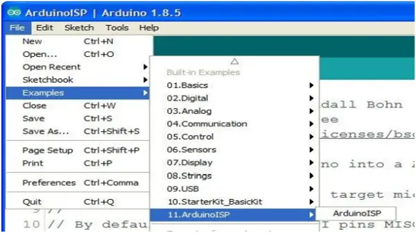
If the process has been successful, you will observe the LED linked to pin 9 of the Arduino smoothly fading in a pulsating manner. This indicates that your Arduino board has been transformed into an ISP programmer, capable of loading code onto your Atmega32 board.
A note on bootloader
Burning a bootloader program into your chip is unnecessary, as clarified in the official datasheet. The Atmega32 is equipped with an on-chip ISP Flash and an On-chip Boot program running on the AVR core. These features enable the reprogramming of the program memory in-system through a Serial Peripheral Interface (SPI).
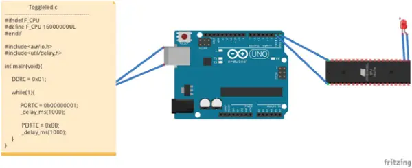
Now, let’s compose a code to be uploaded to our Atmega32 board for blinking the LED connected to pin 22 (PC0). Consult the downloaded datasheet to confirm the correct pin. If you choose to configure your board to use an external 16MHz clock, the program may appear slightly different in the Macros section, as illustrated in the introductory picture.
“`c
#define F_CPU 1000000UL // defining the CPU frequency as 1MHz
#include <avr/io.h> // Including avr’s input-output header library
#include <util/delay.h> // Including utilities for performing delay functions
int main(void) {
DDRC = 0x01; // Declaring pin 22 (PC0) as output
while (1) { // Creating a forever loop to ensure the microcontroller stays active
PORTC = 0b00000001; // Turning PC0 high, illuminating the LED
_delay_ms(1000); // Maintaining the on status for one second
PORTC = 0x00; // Turning off all of port C, including PC0 (our LED)
_delay_ms(1000); // Maintaining the off status for one second
}
}
“`
This code snippet blinks the LED connected to pin 22 (PC0) on the Atmega32 board. Ensure to refer to the datasheet for accurate pin configuration, especially if an external 16MHz clock is utilized, as it may influence the Macros section in the code.
Compiling and Uploading the code
To start, navigate to the “Tools” tab and choose the appropriate board. If you are utilizing the default clock configurations, select the “ATmega32-1 MHz” board. This implies that in your circuit, you do not connect the external crystal oscillator part. In the same “Tools” tab, pick the suitable programmer, opting for “Arduino as ISP” and not “ArduinoISP”. Finally, designate the COM port through which your Arduino is connected. Ensure your Arduino is linked to your PC before clicking on the COM port. Once these settings are in place, click on the “verify” button (the check/tick mark button). When the “save as” window appears, specify the file name without altering the file extension. You may save the file as “toggleled.c”. Allow the compilation process to complete successfully until you see the white text “…sketch uses…”. Now, you are prepared to upload the code to your ATmega32 board. Proceed cautiously.
Go to the “sketch” tab and choose “Upload Using Programmer”. If you opt for the regular upload instead, your code will be directed to the Arduino board rather than the ATmega32 board. If all steps are executed correctly, your status LEDs should blink rapidly, and the LED connected to PC0 should blink every second. At this point, you can disconnect your Arduino circuit and link the minimal power circuitry as outlined below. This demonstrates that your ATmega32 board is now independent of Arduino and is running your toggle LED code. Keep in mind that you can remove the crystal oscillator circuitry if you are using the default 1MHz internal clock configuration, which is recommended. If you wish to explore how to enhance the performance of your Atmega32 by using an external 16MHz clock or its internal 8 or 16MHz clocks, feel free to request an article on that topic.
Conclusion
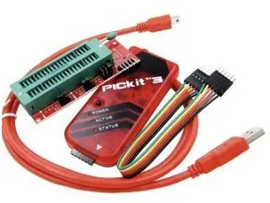
- Why use Arduino instead of traditional ISP programmers?
Arduino boards are more affordable and widely available compared to costly traditional solutions like pickit3 or USBtinyISP AVR. - Can I skip the crystal oscillator and capacitors in the circuit?
Yes, it is optional to exclude the crystal oscillator-capacitors part if you use the default internal clock configuration. - How do I configure the Arduino IDE to recognize the Atmega32 board?
You must replace the boards.txt file with the downloaded version and add new pin definitions by creating a mega32 folder in the variants directory. - Is it necessary to burn a bootloader onto the Atmega32 chip?
No, burning a bootloader is unnecessary because the Atmega32 has on-chip ISP Flash and an On-chip Boot program. - Which menu option should I select to upload code to the Atmega32?
You must choose Upload Using Programmer from the sketch tab, not the regular upload option. - What happens if I select the wrong programmer setting in the Tools menu?
If you do not select Arduino as ISP, your code will be directed to the Arduino board rather than the ATmega32 board. - How can I verify that the Arduino is successfully acting as an ISP?
Success is indicated when the LED linked to pin 9 of the Arduino fades in a pulsating manner after uploading the ArduinoISP sketch. - What is the recommended CPU frequency macro for the default clock setup?
The code defines the CPU frequency as 1MHz using the macro F_CPU 1000000UL for the default configuration.