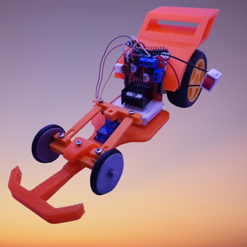
F1(Formula One) Rider is a low-budget car.
Aspiring people with inspiring speeds.
The Rush of excitement is pressing accelerate.
A fast Requires a sharp mind. Some cars are meant to fuel our passion.
Better Ride is an outcome of a better ride.
No hour feels wasted when spent on four wheels.
Small car, but with a large motor.
Start your car and take a ride of it.
Step 1: Video Demonstration
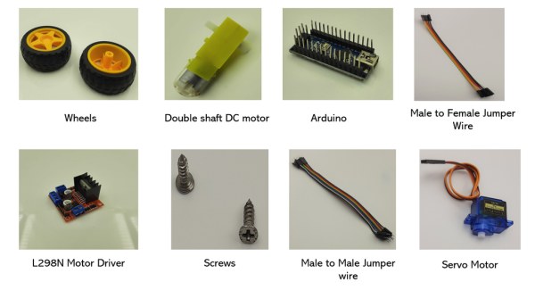
Step 2: Materials Required
Step 3: Arduino
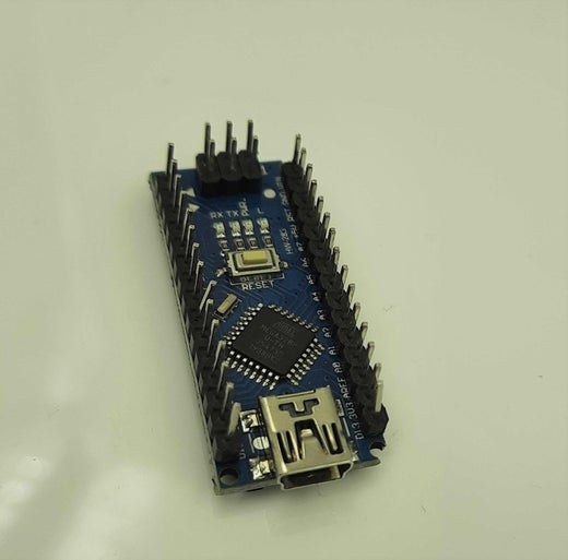
Arduino is an open-source electronics platform based on easy-to-use hardware and software.
It has different input /output pins of the microcontroller chip into digital input/output pins and analog input pins. Now, this board can be programmed using an awesome Arduino IDE (free to download). Arduino comes in different shapes and sizes.
some of the well-known Arduino’s are…
1. Arduino UNO
2.Arduino nano
3.Arduino Pro mini
4.Arduino mega
Arduino is a great tool for developing interactive objects, taking inputs from a variety of switches or sensors, and controlling a lot of lights, motors, and other outputs like a buzzer. Arduino projects can be stand-alone or they can be connected to a computer using USB. There are a variety of projects which can be made using Arduino, like remote control car, automation, and other embedded systems and IoT (Internet of things) based projects. If you are a beginner when it comes to making projects then arduino is really your cup of coffee.
Step 4: L298N Motor Driver
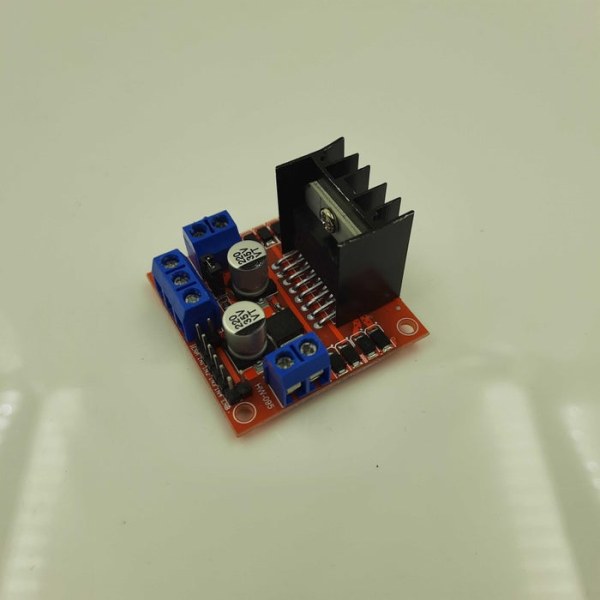
The L298N is a dual H-Bridge motor driver which allows speed and direction control of two DC motors at the same time.
The module can drive DC motors that have voltages between 5 and 35V, with a peak current up to 2A.
H-bridge circuit: Controlling direction(Forward and Backward)
For controlling the rotation direction, we just need to inverse the direction of the current flow through the motor, this method can be done by H bridge circuit.
An H-Bridge circuit contains…
1. Four switching elements
2. Transistors or MOSFET switch the motor at the center forming an H-like configuration.
By activating two particular switches at the same time we can change the direction of the current flow, thus change the rotation direction of the motor.
PWM Signal: Controlling the speed of the motor
A Pulse Width Modulation (PWM) Signal is a method for
generating an analog signal using a digital source. It is possible to control the brightness of the LEDs or speed of a motor, by switching the given voltage ON and OFF very fast and controlling how long it is ON and how long it is OFF. This is done by analog_write block.
Example: When you enter a room and switch on the fan for some time. After some time the fan attains a constant speed and now switches off the fan and lets it come to rest. Now switch on the fan again, but this time you try to toggle the switch between on and off quickly for some time, now we will observe some reduction in the speed of the fan. Repeat the toggling for some more time and you will observe that the speed keeps decreasing with the increase in toggle and this is the main objective of “PWM”.
Terminology:
Duty-cycle: The duty cycle is described as the amount of time the signal switches between ON and OFF conditions. It is mainly written in percentage. Duty cycle = (Active Time of the signal)/(Time-period).
Example: Set the LED to blink 1 second for ON and 1 second
for OFF.
ON time = 1 second.
Total Time Period = On-Time + OFF Time
= 1 second + 1 second
Total Time Period = 2 seconds.
Duty Cycle (in percentage) = ( ON Time/Total Time period)*100
= (1 second/2 second)*100
Duty Cycle = 50%
The output voltage for 50% duty cycle = 3.3 volt * 50 = 1.65 volt
The output voltage on that pin is 1.65 volt.
For a 25% duty cycle, it would be generated with analogWrite(255).
The output voltage on that pin is 0.825V.
For a 75% duty cycle, it would be generated with analogWrite(767).
The output voltage on that pin is 2.475V.
Example: If you intend to run the motor at full speed, you will set the value 1023 i.e. the maximum value it can handle that will ultimately run the motor at full speed. Similarly, setting the value as “0” will be sending no signal and the motor won’t start. And if the motor requires to be run at half speed, then you will set the value 511 or 512 – half of the maximum value that will cause the motor to be running at half speed.
Step 5: Double Shaft DC Motor
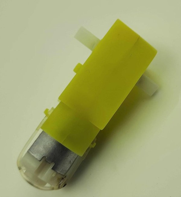
A Motor is a machine which is used to transfer electrical energy to mechanical energy.
In the case of the DC motor, DC voltage is applied on the terminals of the motor which produces a magnetic field inside the motor, the permanent magnet already present in side the motor opposes the magnetic field produced by the coils, movement happens. Now the polls of the magnetic field need to change for the continuous rotation of the motor and it is done by carbon brushes present inside the motor which facilitates the change in polarities.
Step 6: Servo Motor
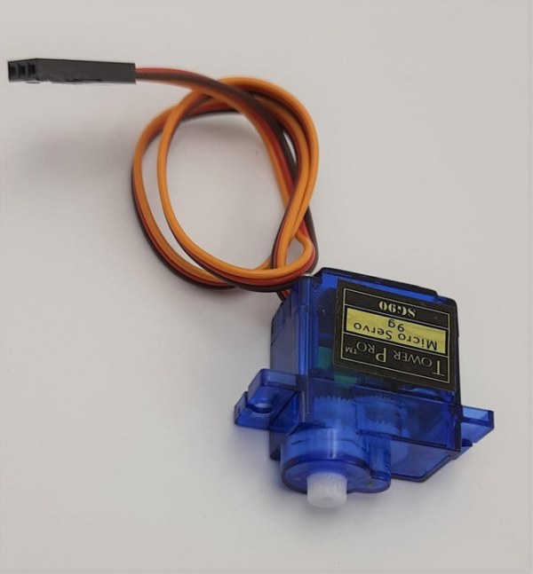
A servo motor is an electrical device that can push or rotate an object with great precision. If we want to rotate an object at some specific angles or distance, then we can use a servo motor.
Orange Wire – Signal Pin
Brown Wire -GND
Red Wire – Power supply
Step 7: Lipo Battery
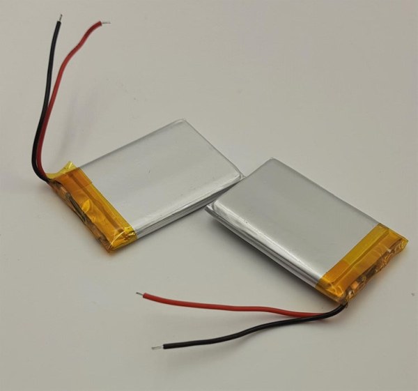
A lithium polymer battery, or more correctly lithium-ion polymer battery (abbreviated as LiPo, LIP, Li-poly, lithium-poly, and others), is a rechargeable battery of lithium-ion technology using a polymer electrolyte instead of a liquid electrolyte.
These batteries provide higher specific energy than other lithium battery types and are used in applications where weight is a critical feature, such as mobile devices, radio-controlled aircraft, and some electric vehicles.
For one lipo battery , Voltage = 3.7 V
current = 1800 mah
For more Voltage , connect two batteries in series = V1 + V2
Total voltage = 3.7 V+3.7 v
= 7.4 V
Step 8: Wiring Diagram
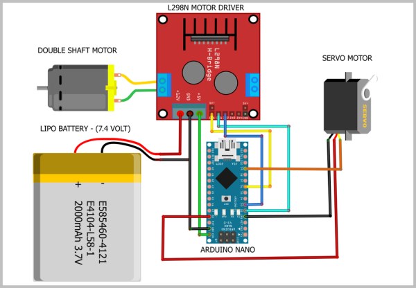
Battery Connections:
The red wire(positive terminal) of the Lipo battery is connected to the input of the L298n Motor Driver.
The black wire(Negative terminal) of the Lipo battery is connected to the input of the L298n Motor Driver.
L298N Motor Driver Connections:
Enable(ENA) pin of the motor driver is connected to the digital write pin(P6) of the Arduino.
The input(IN1) pin of the motor driver is connected to the digital Write pin(P2) of the Arduino.
The input(IN2) pin of the motor driver is connected to the digital Write pin(P3) of the Arduino.
The Output Pin(5V) of the motor driver is connected to the Vin pin of the Arduino.
Servo Motor Connections:
The red wire(positive terminal) of the Servo is connected to the 5V pin of the Arduino.
The black wire(Negative terminal) of the Servo motor is connected to the GND of the Arduino.
The Orange wire(Signal Pin) of the Servo motor is connected to the digital write pin(P9) of the Arduino.
Double Shaft DC Motor Connections:
The Positive terminal of the motor is connected to the l298N motor driver.
The Negative terminal of the motor is connected to the L298N motor driver.
Source: F1 – Rider