Summary of DIY Arduino Battery Spot Welder
This article details the construction of an Arduino Nano-based spot welder for 18650 batteries, utilizing a 12V car battery or LiPo pack. It covers PCB fabrication (V3 with 2oz copper), component assembly including MOSFETs and OLED displays, welding cable creation, 3D printed case integration, and software programming. The guide emphasizes safety measures like fusing and TVS diodes for high-current protection.
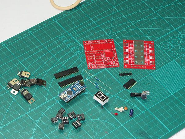
Parts used in the Arduino Spot Welder:
- Arduino Nano
- MOSFET PCB with 2oz copper layer
- Arduino Board PCB
- OLED display
- Rotary encoder
- IRFB7430 MOSFETs
- SMAJ13A-13-F TVS diodes
- Aluminum U-shaped part
- 16mm² flexible welding cables
- 16mm² solid copper wire tips
- Cable shoes and crimp connectors
- Shrink tube
- NO foot switch
- 40x40x10mm 12V fan
- ANL fuse 300A
Due to many requests for the PCBs
I do currently have some PCB Sets and prebuilt kits in stock. Take a look here:
An Arduino Nano based Spot Welder for battery welding This Spot Welder can be used to weld 18650 batteries. It uses a 12V car battery as welding current supply. Typically one 40Ah 440A battery delivers enough current to get good welds with 0.15mm nickel strips and even 0.25mm nickel strips. For thicker nickel strips maybe you will need bigger battery or two in paralell.
The Welder generates a double pulse, where the first one is 12% of the time of the second one by default. Pulse time of the main pulse is adjustable by the rotary encoder and displayed on the screen in ms so you can exactly adjust the time. Its adjustable from 1 … 100 ms by default. (adjustable up to 500ms in the system menu)
Watch the Video to get detailed instructions on how to use it.
https://www.youtube.com/watch?v=CNmvx2JSCvA
Project Files: (BOM, pcb files, aluminum template, arduino code…)
https://github.com/KaeptnBalu/Arduino_Spot_Welder_V3
Update 01.2018 (V3.2)
- the Arduino Board was updated so it is now possible to mount a 3.5mm screw terminal to the input pads.
- the voltage measurement now connects directly to the 12V input pad instead of behind the schottky diode. This guarantuees a more precise voltage measurement.
- the 8 small SMAJ13A-13-F TVS diodes have been removed from the mosfet board. There is now one of these diodes on the Arduino board that protects all mosfet gates at once.
Update 12.2017 (V3.1)
- possibility to solder 4 SMD TVS diodes in parallell on the Mosfet PCB
- enough space to solder 4 through hole TVS diodes instead of SMD diodes if no SMD diodes available
- with 4 diodes installed possible to use with car batteries up to 800CCA
Update 09.2017 (V3)
Completely new version 3 of the Spot Welder released. Improvements in V3:
- Mosfet PCB now with 2oz copper layer and wider traces which connect the high current carrying mosfet legs to the u-shaped aluminum part (still compatible to V2 Arduino Board)
- 7 segment display replaced by OLED display
- potentiometer replaced by rotary encoder
- Menu system to easy adjust the low battery alarm, AutoPulse delay and short pulse time
- powered directly by car battery, no more need for extra power supply
- TVS diode integrated on the mosfet pcb, no external diodes necessary
- upgraded Mosfets to IRFB7430 (they can handle up to 1000A welding current with no problem)
Step 1: Making the PCB (V3)
You can find the Eagle / KiCad files for the PCBs on my Github.
Files for the previous Version
Easyest way is to order the boards at an PCB manufacturer. For example at pcbway.com .There you get 10 boards for about 25 €. The V3 is a bit more expensive because the mosfet board needs to be made with 2oz copper layer. The necessary gerber files for ordering at pcbway.com can be found in my Github.
You can support me by registering through this link http://www.pcbway.com/setinvite.aspx?inviteid=128…
This way you get a 5$ coupon for your order and i get some percent discount on orders for upcoming projects.
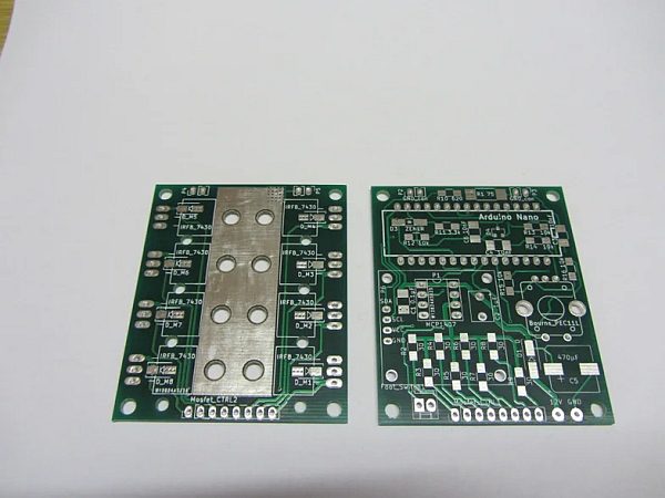
But if you like diy you can also build it on a prototype pcb board with hand wiring. This is how i did the first prototype of the spot welder V1. In the pictures you see a manufactured board looks much cleaner.
Step 2: Optional: Ordering PCBs at a PCB Manufacturer
So many people asked how to order the pcbs. So here is a little instruction.
Ordering the new V3:
For Version 3 you need to order the Mosfet and the Arduino board individually because the Mosfet board needs a 2oz copper layer. The Arduino board can be ordered with standard 1oz copper. Dimensions for the 2 boards the same (50mm x 60mm).
Ordering Tutorial : (pcbway.com)
(V3)
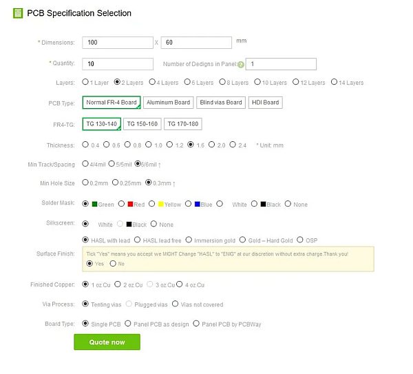
Just go to http://www.pcbway.com/orderonline.aspx (This is the “PCB Instant Quote” Tab on their Website)Type in Board Dimension (50mmx60mm) and quantity (cheapest is 10). Rest of the options don’t need to be changed for the Arduino Board. You can of course change the colour of the Solder Mask (board colour) or the Silkscreen (text on the boards) to what you like. This does not affect the price. You can see how it shoud look like in the picture. Then click quote now, choose your favorite shipping option and click “add to basket”. Now you are asked to add the gerber file. Use the Arduino_Board_V3.zip from my Github.
For ordering the Mosfet Board you need to repeat this process but choose “2 oz copper layer” now. All the other options can stay the same as with the Arduino Board. Use the Mosfet_Board_V3.zip this time.
(V2 or 2.1)
Just go to http://www.pcbway.com/orderonline.aspx . (This is the “PCB Instant Quote” Tab on their Website)Type in Board Dimension (100mmx60mm) and quantity (cheapest is 10). Rest of the options don’t need to be changed. You can of course change the colour of the Solder Mask (board colour) or the Silkscreen (text on the boards) to what you like. This does not affect the price. You can see how it shoud look like in the picture.
Then click quote now, choose your favorite shipping option and click “add to basket”.
Now you are asked to add the gerber file. Use the spot_welder_v2_gerber.zip or spot_welder_v2.1_gerber.zip from my Github.
(ONLY FOR THE OLD VERSION: You can also order each board on its own with the Arduino_Board_Gerber.zip and the Mosfet_Board_Gerber.zip from my github.)
After clicking “submit order now” the guys at pcbway check if everything is ok with the gerber file. This can take only a few hours but can also take some days, depending on how busy they are.
In the Spot_Welder_V2_Gerber.zip Gerber file the “Mosfet” pcb and the “Arduino” pcb are on one
PCB. So ordering 10 pieces means you get 10 full sets. You have to cut the boards in half at the middle line when you receive them.
Step 3: Populating the Arduino PCB (V3)
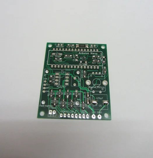
Most parts used for this spot welder are throug hole components. Only some 1206 SMD parts and very few smaller ones are used. So its very easy to solder. If you buy the parts i recommend ordering some more of the smd parts because these little things like to disappear on the floor if your not carefull.
Bill of Materials and Mouser.com Shopping Cart
In the new V3 version i used some 1206 SMD parts and some other sizes to keep the pcb size the same as with the previous V2 version.
To solder this SMD parts i figured it is the easiest way to put some solder on all of the pads. Then hold the SMD part in its position with a tweezer and solder one side. Now the part stays in place and you can solder the other side. Now heat both sides alternating and the part will automatically be pulled in its correct position by the solder.
Take care of the SMD diodes polarity (see the picture). If they are put in the wrong way arround it wont work or may cause damage.
Populating the rest of the through hole parts is very straight forward. Start with the small flat parts and work your way up to the bigger ones. You can see this in the pictures.
Step 4: Populating the Mosfet PCB (V3)
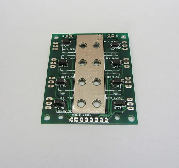
The new mosfet pcb can use a aluminum part instead of the u-bend 16mm2 wire. This makes it much easier to build because you dont need a high power soldering iron and tons of solder. You can of course still use a u-shaped wire instead of the alumium part.
The template for the alumium parts is on my Github. Alumium Parts Template or if you want to buy the ready made aluminum parts take a look here: malectrics.eu
First solder the 8 small tvs diodes to the top of the pcb. (no longer needed on V3.2 and newer)
Then screw the u-shaped alumium part to the pcb with m2.5×8 or m2.5×10 screws and m2.5 nuts. Make sure the screw heads are on the pcb side. This is necessary if your srews are a bit to long (m2.5×10). If you put them in the other way arround they may touch the mosfets later and cause a short circuit. You can also rivet the part to the pcb with 2,4x8mm rivets. Alternatively solder a 16mm2 wire bend to an u-shape to the pcb.
Now you need to install the mosfets and the straight alumium part. In order to do this bend the mosfets legs in a 90 degree angle with some pliers. Use m3x10 screws, m3 nuts and nylon washers to srew the mosfets with the aluminum part to the pcb. Make sure to put nylon washers between the pcb the m3 nuts to make sure they can not scratch the pcb and cause a short circuit. After this solder the mosfets legs to the pcb. Put plenty of solder on the pcb traces that run from the mosfets to the u-shaped aluminum part to make these traces more rigid.
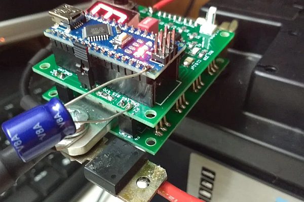
Since you already installed pin headers to the arduino pcb, it is now easy to install the pin headers to the mosfet pcb. Just put the female headers for the mosfet pcb on the ones on the arduino pcb. Lay the Arduino pcb on the table, put the mosfet pcb on top of it and solder the pin headers.
Update 12.2017 (V3.1 and later)
Now 4 TVS protection diodes can be used instead of one. You can use SMD ones (5.0SMDJ13A) or through hole ones (625-5KP13A-E3). The SMD diodes are strong enough for car batteries up to 800CCA.
Solder the 4 TVS diodes on the mosfet board before mounting the aluminum parts. This is much easier than soldering the diodes after the aluminum parts were mounted.
Update 10.2017: (V3)
Although the SMD TVS diode has pretty much the same specs as the bigger
through hole TVS Diode used on the previous Spot Welder versions it seems to struggle with very strong car batteries. There where some fails of the diode reported by users who used 800 CCA or stronger batteries. So i decided to replace the diode with the through hole version, which is a bit more robust.
The BOM of V3 was already updated with the new TVS diode.
Here is how to install it to the pcb:
Scratch of the solder stop paint from the ractangle part with the many holes on the pcb with a box knife and add some solder to the blank copper on the scratched area. We need this because the through hole TVS diode is a bit wider than the SMD version.
Bend the through hole TVS diodes legs 90 degrees as close as possible to the diode and cut them short so the diode can be mounted on the pcb. Then put some solder on the legs and solder the diode to the pcb. Solder the left side first. When the diode stays in place solder the right side (scratched pcb side). Make sure to use a powerful enough soldering iron so you dont heat the diode very long. It is necessary to solder the diode directly on the pcb without extension wires. This way it does the best job eliminating the high voltage spikes.
Step 5: Making Welding Cables
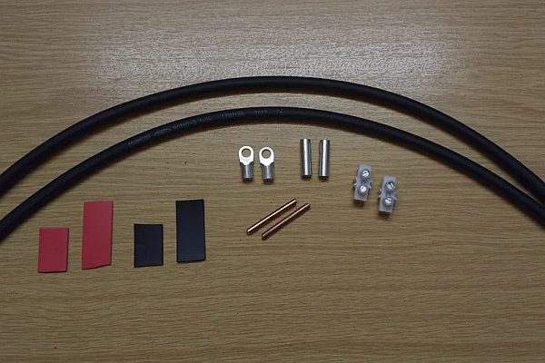
Parts:
- 2pcs 50cm 10 or 16 square mm flexible cable (silicone cable or welding cable H01N2-D)
- 2pcs about 4cm long 16 square mm solid copper wire pieces
- 2pcs cable shoes
- 2pcs cable crimp connectors or luster terminal
- 4pcs shrink tube
Assembly:
- “Sharpen” the solid copper wire pieces. But not to sharp. The tip should have a flat front of about 0.5 to 1mm diameter. An easy way to do this is putting the copper piece in a drill and holding it on a belt sander while the drill is spinning and the belt sander is running.
- Crimp the cable shoes to the cable with a crimping tool. If no crimping tool available you can also use a vise to clamp it. Or solder it with a high power soldering iron.
- Insert the welding cables and the tips in the cable crimp connectors and crimp or solder it. Alternatively you can use luster terminals.
- Add shrink tube or electrical tape
Step 6: The Foot Switch
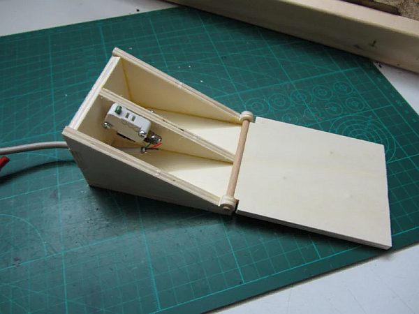
If you dont want to use the Auto Pulse feature where the pulse is triggered automatically after touching the nickel strip with both welding tips you can optional use a foot switch.
For the first welder I built it with a simple wood box and a little switch. But meanwhile i bought a dedicated foot switch . You can get one for example at https://malectrics.eu/
You can use any switch that is NO (normally open) as a foot switch. It does not carry any current.
Step 7: Making a 3D Printed Case
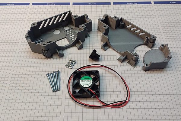
Parts needed:
- 3d printed case
- 3d printed rotary encoder knob
- 40x40x10mm 12V fan
- 4pcs M3x30 screws
- 6pcs M3 nuts
You can find the STL files for the case at thingiverse.
Assembling the case:
A better readable assembly instruction with a picture after every step is available here:
https://malectrics.eu/spot-welder-v3-case-assembly/
Basic steps:
- Before you start to assemble the case you should prepare the Spot Welder. Screw together the two Spot Welder PCBs with the 4pcs M3x25 screws and 12 M3 nylon nuts that come with the prebuilt kit.
- Quick Tip: If the Spot Welder later sits to loose in its case you can adjust the distance between the 2 pcbs with the 2 nylon nuts on the bottom pcb. Just dont put the two pcbs to far apart so the 8-pin and the two 2-pin headers still have good contact. 1 or 2 millimeter gap is ok.
- Cut the wire from the 40mm fan to about 10cm length and solder it to the Spot Welders 12V and GND pad. Also solder a about 20…30cm long positive wire to the 12V pad. This will later be connected to the positive side of your car battery to supply the Spot Welder with +12V.
- Screw the negative welding cable to the straight aluminum part. If you are going to use the Spot Welder with a Lipo battery or dont want to connect it directly to the car battery screw a extension cable to the u-shaped aluminum part.
- The 3d printed case parts come with some support material from the printing process. You need to remove this. Take a box knife and try to get the blade between the support material and the normal printed part. The support matreial should pop of then pretty easy. Repeat this on the other corners. Then remove the support material from the USB port section with some pliers.
- Remove the support material from the m3 nut pockets by inserting a m3 screw from the other side and pushing on the screw with your thumb. The support material should pop out of the pocket then.
- The nuts have a tight fit in the pockets. To get them in put a screw through the hole and screw on a nut. Then tighten the screw so the nut gets pulled into its pocket. Make sure the nut is aligned correctly with the pocket when pulling it in. Do this until all 6 M3 nuts are inserted.
Assembly Option: case with extension cable
- Place the fan in the side of the case like shown in the picture. The
side with the sticker should face to the inside of the case, so the fan blows the air into the case. - Place the Spot Welder in the case and lay together the two bottom parts of the case.
- Put on the top part of the case and make sure the positive cable gets routed through the little cutout on the side. You can choose if you want it to be on the left or right side. Then push together the case parts with one hand and screw in one m3x30 screw with the other hand. Repeat on the other corners.
- Put the 3d printed rotary encoder knob on the rotary encoder. Dont push to hard so you do not damage the rotary encoder or the spot welder pcb.
- The foot switch connector can be plugged in from the top when the case is assembled.
- Now you can connect the Spot Welder to your lipo battery. I recommend to also use the fuse case when connecting to a lipo. The connection in the picture is only an example. You could also cut of the ends of the extension cables and directly solder the battery connector to the cables. The Lipo i recommend is Turnigy Nanotech 5000mAh 3s (11,1V) 65-130C .
- Also isolate the connection to make sure there is no way to produce a short circuit on the lipo.
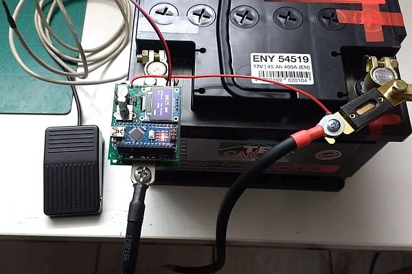
Assembly Option: direct mount to the car battery terminal:
- Screw the U-shaped aluminum part of the Spot Welder directly to your car battery terminal like you would do without the case.
- Insert the fan in the bottom part of the case and put it on the Spot Welder. Hold it so it does not fall off.
- Put on the top part of the case. Now the fan should hold everything together. Insert the 4pcs m3x30 screws.
- Finally tighten the screws.
Step 8: Making a Fuse Case
Why using a fuse or a case ?
If you want to power the Spot Welder with a Lipo battery it is recommended to use a fuse on the positive welding cable. In case the Spot Welder should fail and cause a short circuit and for whatever reason you would not be able to seperate the welding tips this will prevent the lipo battery from burning down your house or exploding.
A 300A fuse works well and can handle higher currents for a short time without problems. Search on ebay for “ANL fuse 300” and you should find it.
First you need to make an adaptor to connect the Lipo battery to the spot welder and the fuse. In my case the battery has a XT90 connector so i made an adapter with this connector, two short pieces of 10 square mm silicone wire and 2 cable shoes.
When everything is connected you need to isolate the fuse. Easiest solution would be to wrap it in electrical tape. But a 3d printed case looks much cleaner.
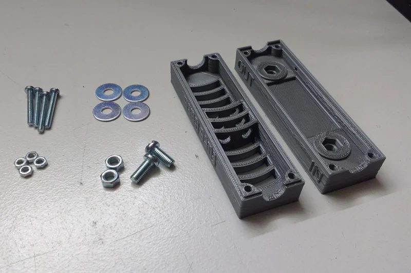
Parts for the fuse case:
You can find the STL files for the case on Thingiverse.
Other parts you need to finish the case:
- 4pcs M3x25mm screws
- 4pcs M3 nuts
- 2pcs M5 nuts
- 2pcs M5x12mm screws
- 4pcs M5 washers
Assembling the case:
- Once you printed the case clean the holes if necessary and insert the 4 m3 nuts.
- Put in the positive cable that will supply power to the Spot Welders +12V input pad through the little hole in the lower case part.
- Push the M5 nuts in theire slots
- Lay the components in the case on the m5 nuts-> washer – fuse – washer – positive welding cable shoe
- Screw in the m5 srew partialy and push the unisolated end of the positive wire under the welding cable shoe
- Tighten the m5 nut completely
- Lay the positive end of the Lipo adaptor you made on the other side of the fuse, put in the screw and tighten it.
- Put on the top part of the case and screw the 2 case halfs together with the 4 m3 screws.
- Finally solder the end of the positive wire to the Spot Welders +12V pad on the Arduino pcb
Step 9: Programming the Arduino
Uploading the new Software (V3.1 or later) is a bit complicated. I made a special tutorial on how to do it on my Blog
https://malectrics.eu/2017/12/13/arduino-spot-welder-software-update-tutorial/
Instructions for older V3:
To upload the Arduino Code to the Arduino you need to do some preperation.
- download the Arduino IDE from https://www.arduino.cc/en/Main/Software
- download the Arduino Code from Github (please click the green “clone or download” button to download the whole project at once, downloading single files can sometimes cause problems)
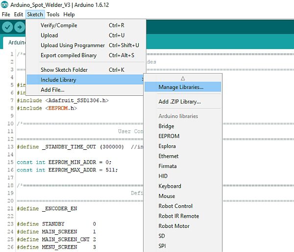
Once you have installed the Arduino IDE you need to add two libraries. The “Adafruit_GFX” and “Adafruit_SSD1306”.
Install them through the library manager in the Arduino IDE (click: Sketch -> Include Library -> Manage Libraries)
Then go to the SSD1306 library folder (on windows typically like this:
C:\Users\Marc\Documents\Arduino\libraries\Adafruit_SSD1306-master ) and open the “SSD1306.h” with a text editor.
In the SSD1306.h you need to define line 51 (#define SSD1306_I2C_ADDRESS 0x3C) and line 69 (#define SSD1306_128_64) . In the latest versio its line 55 and 73.
The code should look like this after you changed it:
#define SSD1306_I2C_ADDRESS   0x3C  // 011110+SA0+RW - 0x3C or 0x3D<br>// Address for 128x32 is 0x3C
// Adress for 128x64 is 0x3D (default) or 0x3C (if SA0 is grounded)
#define SSD1306_128_64<br>//   #define SSD1306_128_32
//   #define SSD1306_96_16
After you have done this dont forget to click save.
Now you can go back to the Arduino IDE and open the Arduino Code from the Github project you downloaded. Connect the Arduino Nano to your computer with an USB cable and it should automatically install the drivers for the Arduino Nano. If it does not connect take a look at this site https://arduino-info.wikispaces.com/Nano-USB-Drivers
If the Arduino is connected correctly a new Com Port should show up in your Arduino IDE under Tools -> Port
Select the new Com Port . Also selct as Board: “Arduino Nano” and Processor: “ATmega328”
Finally click on “sketch -> upload” to write the programm into the Arduino Nano. When it is finished the Display on the Spot Welder should show a low battery warning with the voltage of your USB Port because the default low battery warning is set to 11V.
Step 10: Using the Spot Welder
Now that your finished builing the spot welder here is how to use it.
Basic infos:
- recommended welding battery: car battery 12V 40Ah 440A (or 440CCA) / Lipo battery: 3s 5000mAh with minimum 60C
- Welding cable: 16mm², each about 50cm long
- recommended welding material: 0.1mm to 0.25mm nickel strip
Safety Instructions: (V3)
Only use this product if you have some basic understanding
of electricity. We are dealing with very high currents here which can be dangerous.
The spot welder is capable of up to 1000A welding current for safe operation. Do not use a car battery that can deliver more Amps. For example a 40Ah 440A car battery works fine to weld 0.1mm to 0.25mm nickel strips to batteries.
If you want to use higher currents or longer welding cables you can do this at your own risk. Absolute maximum rating is about 1400A welding current.
Do not connect it wrong way around to the car battery. The U-shaped aluminum part goes to the batteries minus (black) pole.
On the first use set the welding time to 2 or 3ms and see how it welds. Then increase the time until you get good welds. If time is set to high, e.g. 20ms for very thin nickel your nickel material will “explode”.
Optional:
For maximum safety do this before the first use:
turn on the Spot Welder, take a multimeter and measure the resistance between the two aluminum parts. It should show arround 150 Ohm. If it shows 0 Ohm something is shorted out or you got a defective mosfet.
If you dont have a multimeter you can do this: turn on the Spot Welder, switch off the AutoPulse feature, then put a nickel strip on a piece of wood and put one welding tip on the nickel. Then quickly touch the nickel with the other welding tip. If nothing happens you are good. If you burnt a hole in the nickel strip something is wrong.
Quick Start:
- Connect the welding cables and the spot welder according to the connection sketch.
- Connect your foot switch to the spot welder (optional)
- Set the welding time with the rotary encoder (Display shows 1-999 in milli seconds)
- Now you can start welding
The new menu and OLED display features:
The main screen shows the Pulse Time (adjustable by turning the rotary encoder), the battery voltage, the total welds done and if the AutoPulse feature is activated.
You can enter the menu by “clicking” / “pushing on” the rotary encoder.
- Auto Pulse: Here you can turn the AutoPulse on or off and set the delay time. The “AutoPulse” feature automatically activates a pulse after a 2 second delay (default) when both welding tips touch the nickel strip. If it is activated you can not use the foot switch to activate a pulse. The main screen will show “AUTO” in the right bottom corner if it is activated and “MANU” if it is deactivated.
- Btry Alarm: you can set the voltage at which the battery alarm should be triggered (default 11V). If the alarm gets triggered the spot welder will stop working and show a low battery warning until a voltage higher than the set battery alarm is reached. (typically after recharging your battery)
- Shrt Pulse: you can set the duration of the short pulse in % (1 …100) . For example if it is set to 10% and the main pulse is set to 20ms the sort pulse will be 2ms. The short pulse will always be at least 1ms no matter what % value is set. So if the main pulse is 5ms and short pulse is set to 10% it will still be 1ms and not 0.5ms.
Step 11: Adding the “AutoPulse” Feature to Your Existing Spot Welder (only V2.1 and Older)
In the new V3 or V2.2 the “AutoPulse” feature is integrated
You can upgrade your “older” Spot Welder with the new feature pretty easy.
You only need a few parts: (SMD 1206 or wired parts, depending on what you prefer)
- 1x 470 Ohm resistor
- 1x 620 Ohm resistor
- 1x 20 kOhm resistor
- 1x Z-Diode (4,3V 0,5w)
- a piece of thin wire (optional with a connector)
Connect them according to the schematic. (Probe is the mosfets middle Pin) Then upload the new V2.2 Arduino Code to your Arduino Nano.
While the AutoPulse feature is activated you can not use the normal foot switch to activate a pulse. So it is recommended to make the cable that connects to Pin D3 of the arduino removable with a connector. If you do this you need to install the 20k resistor from Pin D3 to GND to make sure the Arduino reads a solid GND signal if the connector is removed.
Alternatively you could flash the Arduino with V2.1 of the Spot Welder software again to disable the AutoPulse feature. Using this method there is no need for the 20k resisor or to make the cable removable with a connector.
Instructions Video: (20k resitor from Pin D3 to GND is missing in the Video, sorry)
Arduino Spot Welder AutoPulse Feature
Step 12: Addon to Power the Spot Welder With the Car Battery (only V2.2 and Older)
Not needed on the new V3 because already included by default
With the help of this very simple addon you can power the Spot Welder
directly from the car battery instead of a 12V power supply.
The only component that needs to be added is a 25V 470µF capacitor. This is enough to keep the voltage of the Arduino board up while the pulse is happening and the car battery drops in voltage. It works for pulse times up to about 50mS. For longer pulse times it is still recommended to use a seperate power supply.
I added the capacitor between the Arduinos Vin Pin and GND. Pay attention to the polarity of electrolytic capactors ! “-” goes to GND and “+” to Vin.
Then you can connect a cable from the voltage input of the PCB to the
car batterys positve terminal to start the Spot Welder. GND input is not needed since it is already connected to the car battery through the aluminum piece.
Oscilloscope measurements to check if the mod is working: (referring to the pictures)
- Voltage at the Arduinos Vin pin while doing a pulse without the extra capacitor:
The Arduino keeps operating even without the extra capacitor, but i would not recommend it.The 22V voltage spike is very short and no problem for the Arduino Nano and the other components to handle.
- Voltage at the Arduinos Vin pin with extra 470µF 25V capacitor and 6mS pulse time:
As you can see in the picture there is no significant voltage drop at this short pulse time.
- Voltage at the Arduinos Vin pin with extra 470µF 25V capacitor and 45mS pulse time:
Here you can see that the voltage drops over the time of the 45mS pulse down to about 8V. That is still enough for the Arduino to operate properly, so about 50mS pulse time is the maximum which schould be used with this mod
Step 13: Populating the PCBs and Adding Wires (Old Version)
All the parts used for this sopt welder are throug hole components. So its very easy to solder. Start with the small parts and work your way up to the bigger ones.
Welding tips are made of 10 square mm thick solid copper wire. The cables are 16 square mm flexible copper wire. Do not make the welding cables to long (max. 50-60cm each). very long cables can cause high inductive voltage spikes which could damage the spot welder.
(update 08.2016)
– In the new Version you have to connect JP1 on the Arduino Board with JP1 on the Mosfet Board and JP2 on the Arduino Board with JP2 on the Mosfet Board. Use pin headers and sockets. These jumpers connect the ground of the two boards. You can see how it is done in the new pictures with the green pcb pretty good.
(update 12.2016)
– added a new picture series of populating the pcb, which should make it more easy to understand.
Step 14: Adding Protection Diodes (only on V2)
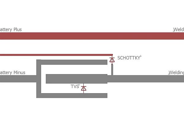
Protection Diodes are not needed in the new V3
Diodes used:
Schottky: VS-100BGQ015 Mouser.com Part: 844-100BGQ015
TVS: 5KP13A-E3/54 Mouser.com Part: 625-5KP13A-E3
Why add diodes ?
The diodes can be used to make the spot welder more reliable when using very high welding currents or long welding cables. They reduce the peak voltage which appears because of the inductance of the welding wires. This is necessary because high voltage spikes could damage or kill your mosfets. A very detailed explanation whats going on can be found here
Adding the diodes:
You can either build some nice wires with cable lugs for the diodes to make it look pretty or solder them directly to the spot welder. The function will be the same. Just make sure to solder on the schottky only with a high power soldering iron so the diode does not become to hot while soldering. The cable for the diodes should be 10mm² ( 7 or 8 awg). For the tvs diode you can also use thinner cable if it is just a very short piece.
Short conclusion of whats going on:
I did some measurements with my 20$ oscilloscope, which is not very accurate, but you can see the effect of the diodes.
The first measurement was done with the normal spot welder with no extra diodes installed.
As you see at the end of the first pulse there is a voltage spike, which reaches up to about 34V. This is no problem as the mosfets are rated for 55V maximum. But if you use longer welding cables or a very strong car battery that can deliver very high current this voltage could probably exceed the 55V. This could then damage or destroy the mosfets.
To get rid of the voltage spikes you can install diodes to the spot welder. You need a TVS and a Schottky diode.
I first did a measurement with only the shottky installed. This lead to a strange oscillating behavior, which can even effect the arduino so the programm crashes. You can see this in the picture with the oscillating voltage.
Last i did a measurement with both diodes (TVS and Schottky) installed. Now the voltage spike at the end of the pulse only reaches about 20V. Even with higher currents or longer welding cables the voltage can not go much hgher because the diodes will prevent this.
Step 15: Frequently Asked Questions – FAQ
What car battery can i use for the Spot welder ?
Recommended is a 12V 40Ah 440A car battery but everything that can deliver 400A to 600A should be fine. I do not recommend to use a so called “deep cycle” battery.They look like a car battery but these are not made to deliver very high currents for a short time. They are meant to deliver little current like 20A to 50A for some hours. They are maybe capable of delivering the high welding current, but could be damaged after some welds.
What nickel strip can i weld ?
You should use 0.1mm to 0.25mm nickel strips. Typically 0.15mm Nickel Strip is good for all standard applications.
0.3mm nickel strip is possible if the pulse time is increased to about 50mS (this time was set with a 440 A or CCA car battery). Also try to use slotted nickel strips if you want to use 0.3mm ones because the slotted ones give you better welding spots with less current or shorter pulse time.
What foot switch can i use ?
You can use any switch that is NO (normally open). The foot switch does
not carry any current, so even very tiny switches will work. (Example foot switch) . Do not wrap the foot switch wire arround a welding cable and try to make a hand switch. This can damage the Spot Welder because of inductive voltage.
How long should the welding cables be ?
Make the cables as short as possible. I recommend 16mm2 (5awg) 0.5m for
each cable. If you make the cables longer the welding pulse will become weaker unless you use thicker cable. Also it is more likely that you damage the Spot Welder with very long cables because of the high inductive voltage that is generated in longer cables.
What power supply do i need for the Arduino board ?
The new V3 does not need a seperate power supply for welding times below
50mS. It can be directly connected to the car batteries or Lipos positive pole. For the older V2 a 12V 2A or 1A power supply works good. Alternatively a 3s Lipo / Liion battery also works perfectly.
Can i use the car battery to power the arduino board ?
Yes in the new V3 you can directly power it from the car battery or Lipo for welding times below 50mS. For V2 or older in the standard configuration you need a seperate power supply or battery.
But if you add a 470µF 25V capacitor between the Arduinos Vin and GND you can power the V2 and older Arduino Board from the car battery. More infos on the Mod
Is it possible to use a PC power supply instead of the car battery ?
No, you need a car battery. A pc power supply can not give you enough Amps to weld. You need about 400A. Typicall power supplys can deliver maximum 50A. Also power supplys usually dont like to be shorted, which is what the welder does.
My computer does not find the Arduino when I plug it in with USB !
If your System does not automatically install the necessary driver you need to install it manually. Check out this page: https://arduino-info.wikispaces.com/Nano-USB-Driv…
Source: DIY Arduino Battery Spot Welder
- What car battery is recommended for this project?
A 12V 40Ah 440A car battery is recommended, though anything delivering 400A to 600A works. - Can I use a PC power supply instead of a car battery?
No, a PC power supply cannot provide the required 400A current needed for welding. - What thickness of nickel strip can be welded?
The device typically handles 0.1mm to 0.25mm strips, with 0.3mm possible using increased pulse times. - How long should the welding cables be?
Cables should be kept short, ideally around 0.5m, to prevent voltage spikes and weak pulses. - Does the V3 version require a separate power supply?
No, the V3 version powers directly from the car battery or LiPo for welding times under 50ms. - What kind of foot switch is compatible?
Any normally open switch works since it does not carry any current during operation. - How do I adjust the welding time on the V3 model?
You adjust the time using the rotary encoder, which displays the duration in milliseconds. - Can I upgrade older versions to include the AutoPulse feature?
Yes, older versions can be upgraded by adding specific resistors and a Z-Diode and flashing new code.