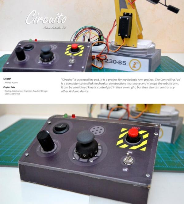
“Circuito” is a DIY controlling pad. It is a Supplementary project for my previous Robotic Arm project. The Controlling Pad is a computer controlled mechanical constructions that help to move and manage any robotic arm depend on servo motors.
It can be considered kinetic control pad in their own right, but they also can control any other Arduino device.
Step 1: Scenario
Circuito is based on Arduino Due.
It makes use for any of Robotic Arm or any Project based on Servo motors easy, of course after programming of visual patches in the Arduino programming language.
One potentiometer, One joystick and three switch inputs are available to modify predefined parameters. Also toggle switch can be used to further control the software or to switch on and off the lights, manual control using potentiometer to control the acceleration of servo motors, audio reactivity using an audio output buzzer to visualize the controlling and movements. The module is fully compatible with Arduino boards, and standalone operation is also possible. Circuito outputs is some of previous prepared serial port orders that can be seen on Arduino serial port monitor and its easy to modify.
I chose to design the front panel as a real printed circuit board since it is a very cost-effective solution and provides interesting design opportunities using the Inkjet color printer, MDF wooden board and soldermask layers.
Step 2: Design
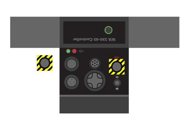
In my opinion the best way to make a life scale product you have Imagine it first, and I designed the controller first on Google SketchUpbecause its a very effective tool to draw your innovation.
Step 3: Tools and Materials
Handtools:
– Soldering iron
– ROTARY TOOL
– Knife – Sandpaper or other sanding equipment
– Screwdriver
– Pliers
Materials:
– Screws
– MDF 4mm 30cm * 21cm
– Male-Female 10cm dupont cables
– Male-Female 10cm dupont cables
– Male-Male 10cm dupont cables
– Shrink Cables
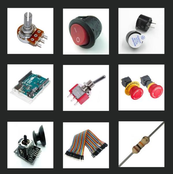
Circuit Components:
– 10k resistor
– LED lights
– Toggle switch 3 pin
– Stop switch
– Joystick Module
– Potentiometer
– On/off switch
– Active Buzzer
– Arduino Uno
Step 4: Making the Board
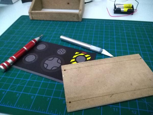
I print out the shape on A4 paper, then I cut it out from MDF board as shown. and to give it good look I just cover the wood with printed paper.
Step 5: Installing the Circuit
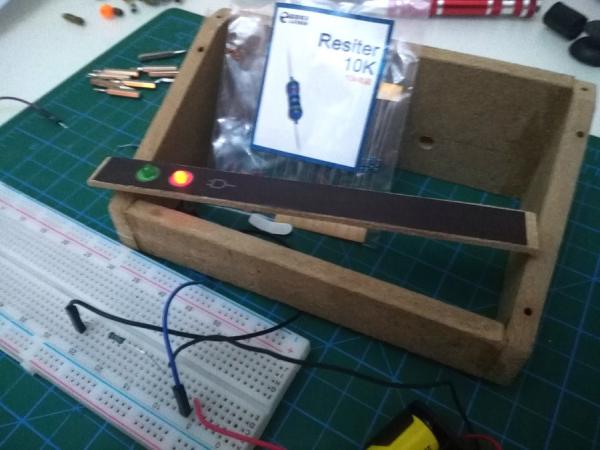
In the first beginning I started with led lights that works as an indicator while using the controller, then I fixed the circuit components as shown.
Step 6: Code
Here is a sample code for how the controller works. in this code I’m shown you how to control multi servo motors which can be in any of your projects.
Source: Circuito Arduino Controller Pad