
In this project I’m showing you how I made my own art robot. The whole concept is to illustrate how we as humans can work together and collaborate with machines and robots to create something new. Both the art style and ethos of the project was inspired by the great pop art artist Andy Warhol.
Warhol was among other things fascinated by commoditization and mass production. This inspired his own art work both in subjects, like Coke bottles, Marilyn Monroe, Campbell Soup cans, and in method – as he used silk screen printing to be able to churn out paintings and art work in his studio The Factory.
I might be severely overstepping, but I like to imagine he would be proud of a robot making art in the style he helped popularize. After all, one of his many famous quotes was: “I want to be a machine”.
Read on to see how I ended up putting this art robot together, so you may learn how to make your very own.
The configuration of this kind of plotter design has many names and there already exists a lot of similar designs, some of which are probably a lot better than the one I made. However I deliberately stayed away from looking at similar designs as the goal of this project was to explore and solve the many expected and unexpected problems along the way. If I used the designs and code already available the project sure could have been finished a lot faster. But my goal with this project was not to finish the robot as quick as I could. The goal of this project was to explore and solve the many expected and unexpected problems along the way. It was a lot of fun!
Supplies
There are a lot of different files needed to complete this project like 3D files, microcontroller code, PCB designs, and a GUI computer program. I have gathered all files I developed and produced in this Github repo to have a single source for all files in their latest iteration and update.
Motors and kinematics
- Metal gear servo motor. Datan B2122
- 2 x Nema 17 stepper motors. Model: 17HS4401N
- 2 x 2GT 20 teeth timing pulleys. 5mm bore hole. For 6mm belt width
- 2 x 2GT timing belts. 6mm wide. 2m long
- 7 x 623ZZ ball bearings. 3x10x4mm
Robot frame and construction
- 20x20mm v-rail. 1500mm long
- At least 4 ratchet or screw clamps
- Access to a 3D printer
- Plaster of paris
- Assortment of M3 nuts, bolts, and washers. You can get away with mostly M3x10mm conicals
PCB and electronics
- Arduino Nano
- 2 x TMC2130 silent stepper drivers
- 4 x 10uF cylindrical aluminum capacitors
- 1 x 330nF 1206 capacitor
- 1 x 100nF 1206 capacitor
- 1 x LM7805 TO-252 linear voltage regulator
- 2 x MDD SS14, DO-214 Schottky barrier diode
- Push button 6.0×3.5mm. Currently not used I just added it in the design as I might need the button later
- 2 x 4-pin female JST headers
- 1 x 3-pin female JST header
- Power supply: 7-35V at least 1.5A
Step 1: How to Make Art
First of all I recommend you watch the video to see the robot in action and how it was set up to create art. As a picture is worth a thousand words, imagine what a video with 30 pictures a second can do.
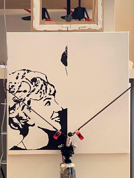
To use the robot for art I clamped a blank canvas onto the robot frame. I then hung the draw head and belts onto the stepper motors at the corners of the robot frame, and centered the draw head, with a permanent marker attached, in its home position. I then connected the robot over USB to the control software running on my computer. Here I loaded a black and white image I created in photoshop, before positioning it approximately where my canvas was located on the robot. To hone in the position I made the robot move in a bounding box formation and tweaked the image location until it was exactly where I wanted it. I then pressed the button to send the image to the robot.
After the robot did its thing I was left with a black and white image. At this point it was time for me to don the beret. I used regular acrylic paint which I thinned with two parts medium, like mod podge. This created an acrylic glaze I could paint over the black details to bring beautiful colors to the canvas, while still preserving the black details and making them shine through the glaze.
Now go make something awesome!
Step 2: Constructing the Robot Frame
In this step we go through everything that attaches onto the robot frame itself. The frame is a 20x20mm v-rail. While developing the robot I used a rail at 100cm long because it was easier to handle on my work desk, but I expanded to a 150cm rail once early development was done. You can use any rail length you want, just adjust the length variable in the Arduino code, we’re going to cover this later.
First thing is to 3D print all the files I’ve made available in the first step. They can be printed very fast at 0.3mm resolution with no infill.
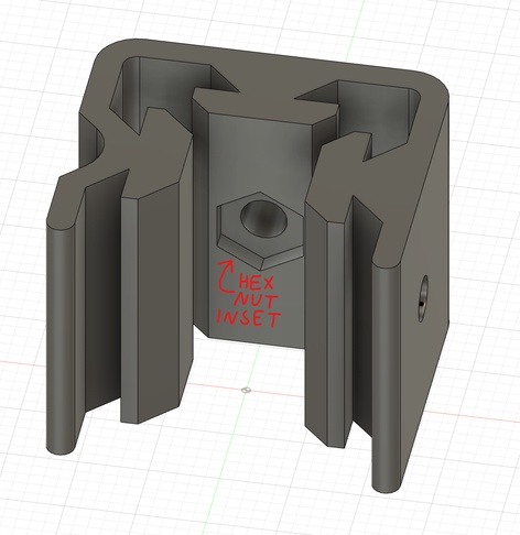
Take a look at the first picture in this step. For all the 3D files with a hexagonal inset you should press fit an M3 nut inside. An M3 screw of whatever length you choose should then screw into the nut from the other side. This pushes the screw into the metal rail and creates a strong mechanical bond which can be loosened if needed.
Homing Key
Screw the Homing Swivel Key onto the Homing Mount making sure the key can still swivel freely. Slide this assembly onto the very center of the robot rail and fasten as described over.
PCB Holder
Print two PCB holders and simply slide them onto the rail. I included the possibility to fasten these with screws, but that’s not really necessary. When The PCB is snapped into the holders at a later stage the tension will keep them securely in place.
Motor Holders
First screw the Nema 17 motors onto the motor holders using M3x10mm screws and a single washer per screw. Next slide the motor holders onto the robot rail and once again fasten with screws, keeping the motors at the edges of the rail. Now is also a good time to attach the pulleys onto the motor shaft.
Robot Frame Assembly
To get the robot out of the way, but still usable at a moments notice I mounted it on top of a tall shelf in my living room. I used an old shelf plate and attached the robot onto the shelf plate with screw clamps. I then clamped this shelf plate on the top edge of my shelf, and used some command strips at the backside of the shelf plate. The command strips give additional fastening preventing the shelf plate from pivoting at the shelf edge, and provides some adjustability where I can easily position the shelf plate forwards or backwards on top of the shelf. This means I can accommodate canvases of varying depth.
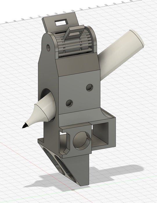
Step 3: Robot Draw Head
Left and Right Hangers
Start by snipping of the included support material and filing down the surface where the supports attached, to give a surface without any remaining bumps. Now insert two 10mm ball bearings into both the left and right hangers.
To make the two hangers attach onto the draw head we use an M3x20mm screw and M3 lock nut at either side of the middle container. This gets put together in the following sandwich assembly:
- M3x20mm screw
- Washer
- Middle container
- Washer
- Right hanger w/ ball bearing
- Washer
- Left hanger w/ ball bearing
- Washer
- Right hanger w/ ball bearing
- Washer
- Middle container
- Washer
- M3 lock nut
You might have to change how many washers you use and their position all depending on how deep you set the bearings into the hangers.
Check that everything is tightly connected but the bearings still are free to move, by dangling the draw head from each of the hanger keys.
Tiny Robot Arm
Now press fit another ball bearing into the side of the draw head. Insert the servo underneath the pen holder, with the rotor closest to the frontside of the draw head. Insert a screw from the servo side poking out through the ball bearing.
Set the tiny 3D printed robot arm onto the screw poking from the ball bearing and onto the servo rotor on the other side. Tighten an M3 nut onto the left side of the draw head, but don’t screw the other side of the arm onto the servo yet. Before you use the servo horn screw to attach the right side of the tiny robot arm you need to power on the servo and set its position to 100. If you don’t have an Arduino at the ready you can wait until you have made the PCB and uploaded the code, to set the servo to its no-draw position.
Optionally you can add ball bearings on each side of the tiny robot arm. I noticed a slight improvement in the lines drawn when I did this.
Step 4: Weights
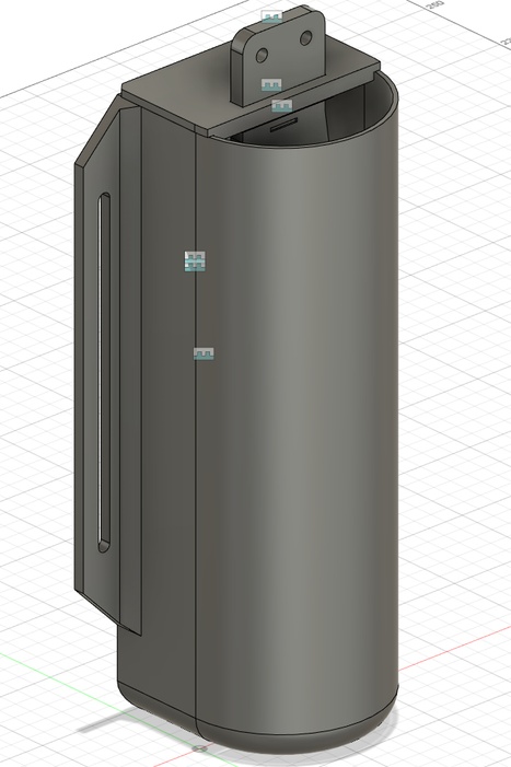
The robots movement is only possible through the generous assistance of gravity. To make the weights for the robot I 3D printed plastic shells which where then filled with plaster. Before the plaster hardened I inserted a 3D printed key, which lets me easily mount the weights onto the robot.
From my experiments I knew I wanted the side weights to be around 300g and the middle weight close to 530g. This combination worked great for the robot size I went with. When I knew the mass I wanted I had to figure out what volume of plaster this would correlate to. So I did some experiments with my plaster and found the density to be: Rho = 1.435 kg/l
Your brands density might vary, but I’m guessing most hobby plasters which is made from 2 parts plaster powder and 1 part water have roughly the same density value.
I used the density value to calculate the volume I needed for the plastic shells, I then designed 3D files which would hold the necessary volume.
Now here’s a pro tip for you: I printed my weight shells in PLA which isn’t waterproof, so the plaster would normally seep through the cracks in the 3D print. To remedy this I just lit a cozy wax candle and used a paint brush to brush a layer of wax on the inside of the 3D print. This waterproofed the shell so the plaster would be securely contained completely inside the shell while it cured.
Now just mix up some plaster and fill the weights until you reach the fill level shown in the pictures. Use the key holders to hold the keys still inside the plaster while it cures. These holders can be removed after 24 hours.
Step 5: Robot Brain
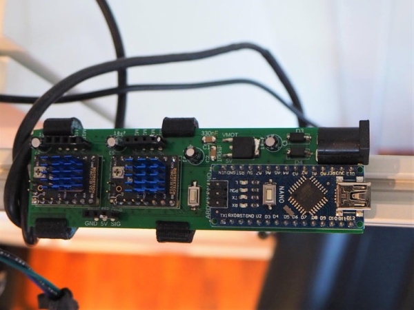
At the center of the robots brain is an Arduino Nano. It handles the incoming commands being transmitted over USB, calculates precisely how to move, sends precise pulse commands to the stepper motors, as well as moves the tiny robot arm up and down to either draw something or just move in a straight line.
In the first step you can download the GERBER files I designed for the robot brain, which I ordered manufactured from JLCPCB.com, who where so kind as to sponsor this project.
The circuit board itself is well labeled and uses regular off the shelf components, all to make it a breeze to solder. As well as the components listed below I soldered male headers to the stepper and servo to allow for easy connect/disconnect of the motors. I soldered corresponding male headers to the servo wire and the two stepper motors.
- Arduino Nano
- 2 x TMC2130 silent stepper drivers
- 4 x 10uF cylindrical aluminum capacitors
- 1 x 330nF 1206 capacitor
- 1 x 100nF 1206 capacitor
- 1 x LM7805 TO-252 linear voltage regulator
- 2 x MDD SS14, DO-214 Schottky barrier diode
- Push button 6.0×3.5mm. Currently not used I just added it in the design as I might need the button later
- 2 x 4-pin female JST headers
- 1 x 3-pin female JST header
To power the electronics I’m using a laptop charger which outputs 19.5V, but you can use whatever power supply you have at the ready as long as it outputs between 7 and 35 volts and at least 1.5A.
When everything is soldered upload the code found in the first step to the Arduino.
Important: You also need to use my fork of the stepper library you can find in my github repo. I had to remove an unneeded feature which caused a bug where the lines weren’t being drawn straight, but with a break point. This took a LOT of debugging to locate and fix haha!
Source: Build a Robot That Creates Art