Summary of Brainwaves Fly a Drone
Summary: This project uses a NeuroSky MindWave Mobile 2 headset, an Arduino Uno, and an HC-05 Bluetooth module to read Attention brainwave levels and control a drone throttle via a servo. High Attention lights LEDs and gradually increases throttle; relaxing causes landing. Steps include wiring and configuring the HC-05, pairing with the MindWave, connecting a servo to the drone controller, wiring the Arduino, uploading provided Arduino code, and testing.
Parts used in the Brainwaves Fly a Drone:
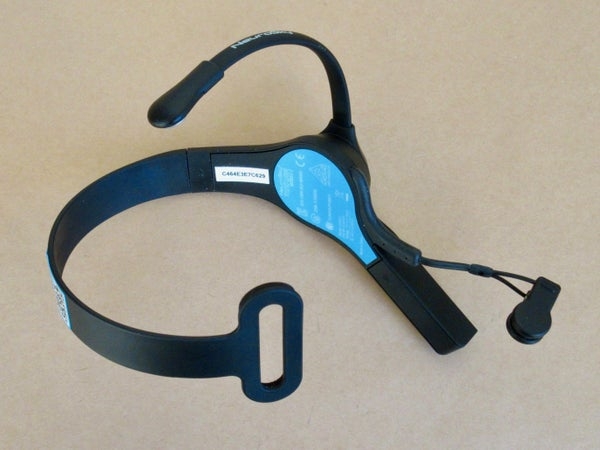
- NeuroSky MindWave Mobile 2 headset and 1 AAA battery
- Computer (used for Arduino IDE)
- Arduino Uno and USB cable
- HC-05 Bluetooth module
- Servo motor (Solarbotics HXT900 Micro Servo used)
- Breadboard and breadboard wires
- Green LED
- Yellow LED
- 2 x 330 ohm resistors
- 2 x 1K ohm resistors
- 2 x 2K ohm resistors
- 10K ohm potentiometer
- Power source about 5 volts (e.g., 3 AA batteries in a holder)
- 2 elastics (for servo to controller attachment)
- Toothpicks (a few, for H-shaped connector)
- Small piece of thin cardboard
- Scissors
- Glue
- Tape
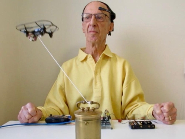
Drones are fun to fly, and it’s possible to do limited flying using brainwaves. The headset senses my brainwaves and transmits them to a small computer. When I increase my attention level, the computer converts the signals and passes them to the drone’s controller, which I have connected to the computer. When I relax my mind, the drone lands.
The headset is a NeuroSky MindWave Mobile 2, the computer is an Arduino Uno microcontroller, and the Bluetooth module is an HC-05.
For some reason (?) the YouTube video will not embed into this instructable. Here is the link:
There are 6 main steps in this project:
- Wire the HC-05 to the Arduino.
- Configure the HC-05 and pair it with the MindWave.
- Connect the servo to the drone’s controller.
- Wire the Arduino.
- The Arduino Sketch (The Code)
- Upload the Arduino sketch and use it.
If you’re not familiar with these devices, the following links may be useful:
Getting started with Arduino: https://www.arduino.cc/en/Guide
https://www.instructables.com/A-Beginners-Guide-to-Arduino/
Online Arduino class: https://www.instructables.com/Arduino-Class/
NeuroSky’s website: https://store.neurosky.com/pages/mindwave
http://developer.neurosky.com/docs/doku.php?id=start
Differences between the 4 models of MindWave: http://support.neurosky.com/kb/mindwave-mobile-2/whats-the-difference-between-mwm2-mwm-and-original-mwm
NeuroSky’s Arduino project (it uses a BlueSMiRF Blluetooth module instead of the HC-05 I used. The sample code (which runs on an Arduino) should work okay regardless of the type of Bluetooth module.):
http://developer.neurosky.com/docs/doku.php?id=mindwave_mobile_and_arduino
Supplies
PARTS for the electronics:
- NeuroSky MindWave Mobile 2 headset and 1 AAA battery
- A computer (I used an Apple iMac)
- Arduino Uno or another model and its USB cable
- HC-05 Bluetooth module
- Servo motor (I used a Solarbotics HXT900 Micro Servo)
- Breadboard and breadboard wires
- Green LED and yellow LED
- 2 x 330 ohm resistors
- 2 x 1K ohm resistors
- 2 x 2K ohm resistors
- 10K ohm potentiometer
- Power source, about 5 volts, such as 3 AA batteries in a holder
PARTS for the servo connection to the drone’s controller:
- 2 elastics
- a few toothpicks
- small piece of thin cardboard
- scissors
- glue
- tape
Step 1: Wire the HC-05 to the Arduino
A few websites describe how to set up an HC-05 Bluetooth module for the NeuroSky MindWave, but none of the methods worked for me. Maybe the reason was that my HC-05 has a newer version of firmware? Or my MindWave is a newer model? Anyway, I researched other Internet websites for info about configuring and pairing an HC-05, and eventually figured out how to do it.
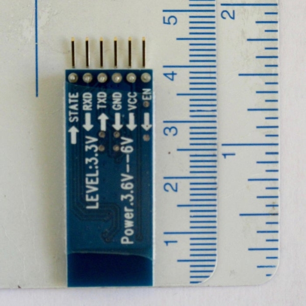
Photos of the front and back of an HC-05 are shown.
Plug the HC-05 into the breadboard and connect it to the Arduino as described below and shown in the photo.
- HC-05‘s RXD to pin 11 via a voltage divider made from 2 resistors,
- TXD to pin 10,
- GND to GND,
- EN to pin 9 via a voltage divider made from 2 resistors.
- Do not connect HC-05’s VCC yet.
The reason for using voltage dividers is that HC-05‘s RXD and EN tend to die after getting 5 volts for some time, and the voltage should be reduced to 3.3 volts. The voltage divider consists of a 1K ohm resistor with one end connected to Arduino’s 5 volts and the other end to a 2K ohm resistor with its other end connected to GND. Two voltage dividers are needed, one for RXD and the other for EN.
Step 2: Configure and Pair the HC-05
Find the sticker on the MindWave showing the Bluetooth address. This will be needed in one of the HC-05 commands. If your MindWave doesn’t have a sticker, NeuroSky’s Arduino project describes how to determine it, under the title “Determining the MAC address of your MindWave Mobile” in this website: http://developer.neurosky.com/docs/doku.php?id=mi…
1. Start the Arduino app on the computer.
2. Connect the Arduino’s USB cable to the computer. The green light on the Arduino should be on.
3. Download the sketch .ino file located at the end of this step, or copy the following code, which relays data between Arduino’s Serial Monitor and the Bluetooth module, and paste it into a new Arduino sketch. (When writing these instructions, the instructables system sometimes dropped part of the #include statement located at the beginning of the code. It should be #include followed by a left arrow < followed by SoftwareSerial.h followed by a right arrow >).
I found the code in the following YouTube video: https://www.youtube.com/watch?v=lTvYbnr6aBo
#includeSoftwareSerial BT(10,11);
void setup() { pinMode(9,OUTPUT); digitalWrite(9,HIGH); Serial.begin(38400); BT.begin(38400); Serial.println(“Bluetooth AT command mode”); } void loop() { if(BT.available()) Serial.write(BT.read()); if(Serial.available()) BT.write(Serial.read()); }
4. Upload the sketch to the Arduino.
5. While pressing the small button over the EN pin on the HC-05, connect HC-05‘s VCC to Arduino’s +5v and keep the button pressed for a few seconds until the red light on the HC-05 begins to blink on for 2 seconds and off for 2 seconds.
6. Open the Arduino’s Serial Monitor (top right corner in the Arduino app window) on the computer and set the options in the lower right corner to “Both NL & CR” and “38400” baud rate.
7. Click inside the input line of the Serial Monitor window. Type AT on the computer’s keyboard and press Return. If the response is “OK” then continue. If it’s not “OK” then try again. It sometimes doesn’t work the first time.
8. Power-on the MindWave. The light beside the switch is steady blue on the MindWave Mobile 2. Earlier models of the MindWave behave differently.
9. Type AT commands as shown below. The response should be “OK” after each command.
AT+UART=57600,0,0 Defines the baud rate used by the MindWave.
AT+ROLE=1 Sets the HC-05 as Master rather than Slave.
AT+PSWD=0000 Sets the password used by the MindWave.
AT+CMODE=0 To connect the HC-05 to a specific device.
AT+CLASS=0 Specifies the Class of Device.
AT+INQM=1,9,48 Sets parameters for pairing.
AT+INQ to see if the HC-05 recognizes the MindWave. This may take 15-20 seconds to find the MindWave. One of the displayed devices should have the same address as on the MindWave sticker, in the format xxxx:xx:xxxxxx. This address is used in the next 3 commands (shown as addr) except the colons must be replaced by commas.
AT+PAIR=addr,30 (Strangely, there was no “OK” response here.)
AT+BIND=addr (The red light on HC-05 still blinks on for 2 seconds and off for 2.)
AT+LINK=addr
10. The red light on the HC-05 should make 2 quick blinks every 3-4 seconds. The first time I did the LINK command, the red light didn’t change. So I double-checked the wire pins were pushed down properly on the Arduino and breadboard, pulled out the +5v wire from the HC-05, did step #5, and typed the PAIR, BIND and LINK commands. This time, the red light changed to 2 quick blinks every 3-4 seconds. This means the devices are paired. Next time you use the devices, they will pair automatically within a few seconds.
11. Disconnect the HC-05’s TXD wire from the Arduino’s pin 10 and connect it to the Arduino’s RX (pin 0), disconnect the HC-05‘s wires from the voltage dividers and remove them, and remove the resistors used as the voltage dividers. The wiring should now be as shown in the photo.
12. Close the Serial Monitor.
13. Power-off the MindWave.
14. Disconnect the USB cable from the Arduino or the computer.
15. Quit the Arduino app.
Step 3: Connect the Servo to the Drone’s Controller
There are two ways of connecting to the drone controller:
- The controller could be hacked as follows: Remove the potentiometers that the joysticks are attached to, and connect the Arduino to the controller’s circuit board where the middle pins of the potentiometers had been connected. The following website has excellent instructions for this hack: https://www.hackster.io/WesleyCMD/mind-control-drone-c8b28a The project uses only the Attention level signal from the brainwave headset.
- My drone controller is so small that I thought the potentiometers would be tiny and too difficult to extract. So, I decided to use a servo to move the joystick for the drone’s throttle, based on the Attention level signal.
The Attention level is easy to obtain and work with. When I researched NeuroSky projects on the Internet, I found that most projects used only Attention. Meditation is also easy to use, but it is related to Attention. Generally, if Attention is high then Meditation is low and vice versa. Some people may be able to set their Attention and Meditation levels independently, but based on my research on the Internet, this is unusual.
Eye-blinking can also be detected by the MindWave headset, but from what I have read, obtaining the Blinking signals and making use of them seems much more complicated than the Attention and Meditation signals.
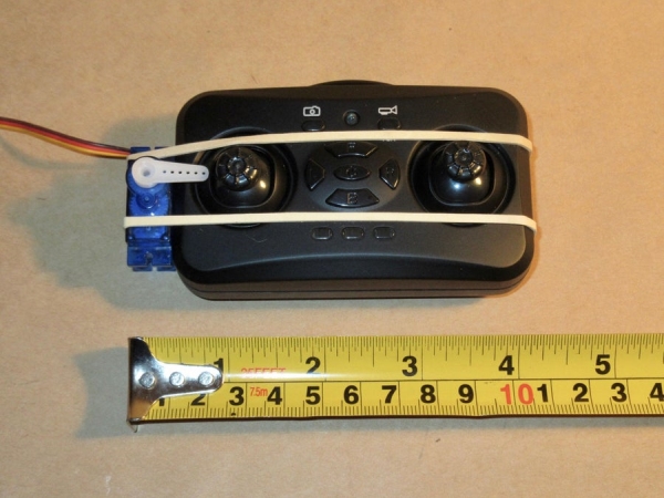
The first photo shows how the servo is attached to my controller by two elastics. As you can see, there is a gap between the servo arm and the joystick. The second photo shows an H-shape made from pieces of toothpicks glued together and glued to a small piece of thin cardboard. One end is then taped to the servo arm and the other end fits the joystick, as shown in the third and fourth photos.
If you decide to do something similar, the connection between the servo arm and joystick could be very different, depending on the size and shape of your drone controller.
Step 4: Wire the Arduino
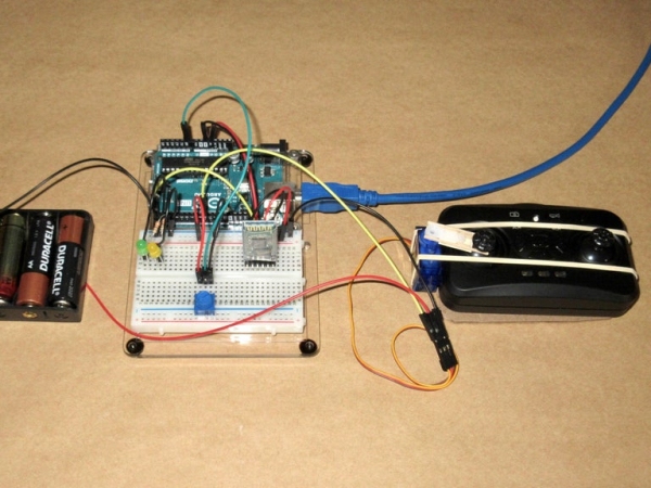
Starting with the circuit after step #11 in Configuring and Pairing the HC-05 (above) the additional wiring should be as described and shown in the photo.
- One wire of a 330 ohm resistor to pin 2 and the other wire to the long wire of the green LED. The short wire of the green LED goes to minus on the breadboard.
- One wire of a 330 ohm resistor to pin 4 and the other wire to the long wire of the yellow LED. The short wire of the yellow LED goes to minus on the breadboard.
- Pin 9 goes to the signal wire of the servo. It’s the yellow one.
- Orange wire of the servo goes to plus of the separate power source.
- Brown wire of the servo goes to minus on the breadboard.
- The minus of the separate power source goes to minus on the breadboard.
- 10K potentiometer to breadboard plus and minus, with middle pin to analog pin 0
To double-check, the following 7 wires should be connected to the breadboard’s minus: the Arduino’s GND, the short wires of both LEDs, the servo, the separate power source, the HC-05 and the potentiometer. And the following 3 wires should be connected to the breadboard’s plus: the Arduino’s +5V, the HC-05 and the potentiometer.
Step 5: The Arduino Sketch (The Code)
When Attention is high, the code will turn on 2 LEDs and move a servo arm attached to the throttle joystick of a drone controller.
The code has the following main functions:
- Read data from the MindWave.
- Obtain Attention data and display it in the Serial Monitor on the computer.
- Turn on the yellow LED when Attention is more than 50 and off if lower, and turn on the green LED when Attention is more than 70 and off if lower.
- Move the servo arm when Attention is more than 50. The movement has a maximum of 30 degrees because my throttle joystick doesn’t allow any more than that. The potentiometer adjusts the maximum (no higher than 30 degrees). With a fully charged drone battery, the potentiometer should be at its mid-point. As the drone’s battery is being used up, the potentiometer should be turned higher.
- The code makes the drone lift gradually by increasing the throttle to 30% of the maximum set by the potentiometer for 0.3 seconds, to 50% for another 0.3 seconds, to 70% for 0.3 seconds, and finally to 100%. Before including this feature, the drone would lift very quickly and become unstable when it suddenly reached the end of the string. And the reason for the string is to keep the drone from flying away upwards or sideways.
The Arduino sketch (the code) may be downloaded as the .ino file located at the end of this step, or the following code could be copied and pasted into a new Arduino sketch. (When writing these instructions, the instructables system sometimes dropped part of the #include statement located at the beginning of the code. It should be #include followed by a left arrow < followed by Servo.h followed by a right arrow >).
/*
When Attention is high, this code will turn on 2 LEDs and move a servo arm
attached to the throttle joystick of a drone controller. December 26, 2020.
Yellow LED on when Attention is more than 50
Green LED on when Attention is more than 70
Servo moves to position set by potentiometer (between 0 and 30 degrees)
Hardware: Arduino with HC-05 Bluetooth and NeuroSky MindWave Mobile 2
*/
#include<Servo.h>
#define BAUDRATE 57600
#define YLED 4
#define GLED 2
////////// Variables
Servo myservo;
byte payloadData[32] = {0};
byte Attention=0;
byte checksum=0;
byte generatedchecksum=0;
int Plength;
int val; // variable to read the value from the analog pin
int val2; // variable to hold temporary value for gradual ascent
int countup = 0; // counter for steps in gradual ascent
int potpin = 0; // analog pin used to connect the potentiometer
////////// Arduino setup
void setup() {
Serial.begin(BAUDRATE); // baud rate for the MindWave
pinMode(YLED, OUTPUT); // initialize the LED pins as output
pinMode(GLED, OUTPUT);
Serial.println(“Attention Values”); // display title in Serial Monitor
myservo.attach(9); // attach the servo on pin 9 to the servo object
myservo.write(0); // move the servo to 0 degrees
delay(15); // give the servo time to move there
}
////////// Read data from the MindWave
byte ReadOneByte()
{
int ByteRead;
while(!Serial.available());
ByteRead = Serial.read();
return ByteRead;
}
////////// Main program
void loop()
{
////// Look for sync bytes and read data from the MindWave
while (1)
{
if(ReadOneByte() == 170)
{
if(ReadOneByte() == 170)
{
Plength = ReadOneByte();
if(Plength == 32)
{
generatedchecksum = 0;
for(int i = 0; i < Plength; i++)
{
payloadData[i] = ReadOneByte(); //Read payload into memory
generatedchecksum += payloadData[i] ;
}
generatedchecksum = 255 – generatedchecksum;
checksum = ReadOneByte();
////// Obtain Attention data and display it in the Serial Monitor
if(checksum == generatedchecksum)
{
if (payloadData[28]==4)
{
Attention = payloadData[29];
Serial.println(Attention, DEC);
////// Light the LEDs and move the servo
if (Attention>50)
{
digitalWrite(YLED, HIGH); // turn yellow LED on
val = analogRead(potpin); // read the value of the potentiometer
// (value between 0 and 1023)
// The potentiometer adjusts the maximum throttle. With a fully
// charged drone battery, the potentiometer should be at its
// mid-point. As the drone’s battery is being used up, the
// potentiometer should be turned higher.
val = map(val, 0, 1023, 0, 30); // scale it to use it with the servo
// (value between 0 and 30)
// This makes the servo move a maximum of 30 degrees. My
// throttle joystick doesn’t allow any more movement than that.
//// gradual ascent, slowly increasing the throttle
if (countup == 0) {
countup = 1; // First, set throttle to 30% for 0.3 seconds
val2 = val*0.3;
myservo.write(val2);
delay(300);
}
else {
if (countup == 1) {
countup = 2; // Now, set throttle to 50% for 0.3 seconds
val2 = val*0.5;
myservo.write(val2);
delay(300);
}
else {
if (countup == 2) {
countup = 3; // Then, set throttle to 70% for 0.3 seconds
val2 = val*0.7;
myservo.write(val2);
delay(300);
}
else {
if (countup == 3) {
myservo.write(val); // Finally, set throttle to 100%
delay(15);
}
else{
}
}
}
}
}
else {
digitalWrite(YLED, LOW); // turn yellow LED off if Attention is 50 or lower
countup = 0; // reset the counter
myservo.write(0); // set throttle to 0
delay(15);
}
if(Attention>70) // turn green LED on if Attention is over 70
{
digitalWrite(GLED, HIGH);
}
else // turn green LED off if Attention is 70 or lower
{
digitalWrite(GLED, LOW);
}
}
}
}
}
}
}
}
Source: Brainwaves Fly a Drone
- What headset is used in the project?
The NeuroSky MindWave Mobile 2 headset is used. - Can the HC-05 be configured to pair with the MindWave?
Yes; the HC-05 is configured with AT commands and paired using the MindWave Bluetooth address. - How does the project read Attention from the MindWave?
The Arduino reads payload packets from the MindWave over Bluetooth and extracts the Attention byte from payloadData indices 28 and 29 when valid. - What happens when Attention is above thresholds?
The yellow LED turns on if Attention is over 50, the green LED turns on if Attention is over 70, and the servo moves to increase throttle when Attention is over 50. - How is the servo connected to the drone controller?
The servo is mechanically attached to the throttle joystick using elastics and an H-shaped toothpick/cardboard linkage to push the joystick. - Does the code prevent sudden drone lift?
Yes; the code ramps throttle in steps (30%, 50%, 70%, 100%) with delays to create a gradual ascent. - What voltage precautions are used for HC-05 connections?
Voltage dividers are used on HC-05 RXD and EN to reduce Arduino 5V signals to about 3.3V to avoid damage. - What pins are used between HC-05 and Arduino during configuration?
During AT mode: HC-05 RXD to Arduino pin 11 via voltage divider, TXD to pin 10, GND to GND, EN to pin 9 via voltage divider; VCC is connected after entering AT mode procedure. - How is the potentiometer used?
The 10K potentiometer adjusts the servo maximum travel (mapped 0–30 degrees) to calibrate throttle range. - Does the project use Meditation or Blink signals?
No; the project primarily uses the Attention signal; Meditation and Blink are noted but not used.