In the 1970’s, a psychic named Uri Geller introduced spoon-bending using his mental powers and became famous for it.
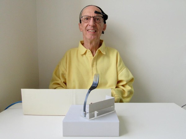
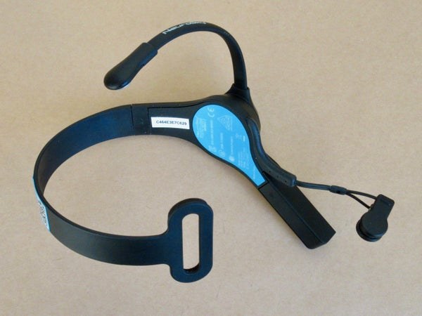
Well, I don’t claim to be a psychic, but I thought it would be fun to be able to bend a spoon or fork using my brainwaves, and this would be a good first project utilizing mental powers. After some research on the Internet, the idea developed into a plan and then a project. A NeuroSky headset can sense brainwaves and transmit them to an Arduino microcontroller using Bluetooth. The Arduino can drive a servo motor which pulls a thread connected to a fork, bending it.
If you’re not familiar with these devices, the following links may be useful:
Getting started with Arduino https://www.arduino.cc/en/Guide
https://www.instructables.com/A-Beginners-Guide-to…
Online Arduino class: https://www.instructables.com/Arduino-Class/
NeuroSky’s website: https://store.neurosky.com/pages/mindwave
http://developer.neurosky.com/docs/doku.php?id=sta…
Differences between the 4 models of MindWave: http://support.neurosky.com/kb/mindwave-mobile-2/…
NeuroSky’s Arduino project (it uses a BlueSMiRF Blluetooth module instead of the HC-05 I used. The sample code (which runs on an Arduino) should work okay regardless of the type of Bluetooth module.):
http://developer.neurosky.com/docs/doku.php?id=min…
There are 4 main steps in this project:
- Configure the HC-05 and pair it with the MindWave.
- Make the fork mechanism.
- Wire the Arduino.
- Upload the Arduino sketch (the code) and use it.
Supplies
PARTS for the electronics:
- NeuroSky MindWave Mobile 2 headset and 1 AAA battery
- A computer (I used an Apple iMac)
- Arduino Uno or another model and its USB cable
- HC-05 Bluetooth module
- Servo motor (I used a Solarbotics HXT900 Micro Servo)
- Breadboard and breadboard wires
- Green LED and yellow LED
- 2 x 330 ohm resistors
- 2 x 1K ohm resistors
- 2 x 2k ohm resistors
- Power source, about 5 volts, such as 3 AA batteries in a holder
PARTS for the fork mechanism:
- Small box or case to hold the fork and servo. It could be rigid plastic, wood or metal
- Plastic fork or spoon
- Bolt and nut to attach the fork
- Twist-tie to attach the servo
- Thread to connect the fork to the servo, about 12” long (30 cm)
- Q-tip (with the ends cut off) or something similar to hold the thread in a good position
TOOLS
– Drill to make holes in the fork and box
– File to make the fork flexible
– Glue to hold the Q-tip in place
– Screwdriver
Step 1: Configuring and Pairing the HC-05, Part 1: Wiring the Arduino
A few websites describe how to set up an HC-05 Bluetooth module for the NeuroSky MindWave, but none of the methods worked for me. Maybe the reason was that my HC-05 has a newer version of firmware? Or my MindWave is a newer model? Anyway, I researched other Internet websites for info about configuring and pairing an HC-05, and eventually figured out how to do it.
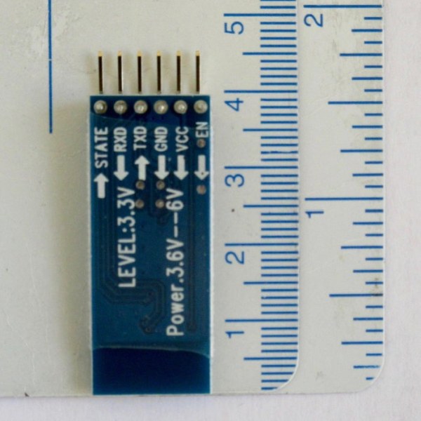
Photos of the front and back of an HC-05 are shown.
Plug the HC-05 into the breadboard and connect it to the Arduino as described below and shown in the photo.
- HC-05‘s RXD to pin 11 via a voltage divider made from 2 resistors,
- TXD to pin 10,
- GND to GND,
- EN to pin 9 via a voltage divider made from 2 resistors.
- Do not connect HC-05’s VCC yet.
The reason for using voltage dividers is that HC-05‘s RXD and EN tend to die after getting 5 volts for some time, and the voltage should be reduced to 3.3 volts. The voltage divider consists of a 1K ohm resistor with one end connected to Arduino’s 5 volts and the other end to a 2K ohm resistor with its other end connected to GND. Two voltage dividers are needed, one for RXD and the other for EN.
Find the sticker on the MindWave showing the Bluetooth address. This will be needed in one of the HC-05 commands. If your MindWave doesn’t have a sticker, NeuroSky’s Arduino project describes how to determine it, under the title “Determining the MAC address of your MindWave Mobile” in this website:
http://developer.neurosky.com/docs/doku.php?id=mindwave_mobile_and_arduino
1. Start the Arduino app on the computer.
2. Connect the Arduino’s USB cable to the computer. The green light on the Arduino should be on.
3. Download the sketch .ino file located at the end of this step, or copy the following code, which relays data between Arduino’s Serial Monitor and the Bluetooth module, and paste it into a new Arduino sketch. (When writing these instructions, the instructables system sometimes dropped part of the #include statement located at the beginning of the code. It should be #include followed by a left arrow < followed by SoftwareSerial.h followed by a riight arrow >).
I found the code in the following YouTube video:
#include<SoftwareSerial.h>
SoftwareSerial BT(10,11);
void setup()
{
pinMode(9,OUTPUT);
digitalWrite(9,HIGH);
Serial.begin(38400);
BT.begin(38400);
Serial.println(“Bluetooth AT command mode”);
}
void loop()
{
if(BT.available())
Serial.write(BT.read());
if(Serial.available())
BT.write(Serial.read());
}
4. Upload the sketch.
5. While pressing the small button over the EN pin on the HC-05, connect HC-05‘s VCC to Arduino’s +5v and keep the button pressed for a few seconds until the red light on the HC-05 begins to blink on for 2 seconds and off for 2 seconds.
6. Open the Arduino’s Serial Monitor (top right corner in the Arduino app window) on the computer and set the options in the lower right corner to “Both NL & CR” and “38400” baud rate.
7. Click inside the input line of the Serial Monitor window. Type AT on the computer’s keyboard and press Return. If the response is “OK” then continue. If it’s not “OK” then try again. It sometimes doesn’t work the first time.
8. Power-on the MindWave. The light beside switch is steady blue on the MindWave Mobile 2. Earlier models of the MindWave behave differently.
9. Type AT commands as shown below. The response should be “OK” after each command.
AT+UART=57600,0,0 Defines the baud rate used by the MindWave.
AT+ROLE=1 Sets the HC-05 as Master rather than Slave.
AT+PSWD=0000 Sets the password used by the MindWave.
AT+CMODE=0 To connect the HC-05 to a specific device.
AT+CLASS=0 Specifies the Class of Device.
AT+INQM=1,9,48 Sets parameters for pairing.
AT+INQ to see if the HC-05 recognizes the MindWave. This may take 15-20 seconds to find the MindWave. One of the displayed devices should have the same address as on the MindWave sticker, in the format xxxx:xx:xxxxxx. This address is used in the next 3 commands (shown as addr) except the colons must be replaced by commas.
AT+PAIR=addr,30 (Strangely, there was no “OK” response here.)
AT+BIND=addr (The red light on HC-05 still blinks on for 2 seconds and off for 2.)
AT+LINK=addr
10. The red light on the HC-05 should make 2 quick blinks every 3-4 seconds. The first time I did the LINK command, the red light didn’t change. So I double-checked the wire pins were pushed down properly on the Arduino and breadboard, pulled out the +5v wire from the HC-05, did step #5, and typed the PAIR, BIND and LINK commands. This time, the red light changed to 2 quick blinks every 3-4 seconds. This means the devices are paired. Next time you use the devices, they will pair automatically within a few seconds.
11. Disconnect the HC-05’s TXD wire from the Arduino’s pin 10 and connect it to the Arduino’s RX (pin 0), disconnect the HC-05‘s wires from the voltage dividers and remove them, and remove the resistors used as the voltage dividers. The wiring should now be as shown in the photo.
12. Close the Serial Monitor.
13. Power-off the MindWave.
14. Disconnect the USB cable from the Arduino or the computer.
15. Quit the Arduino app.
Step 3: Making the Fork Mechanism
The first step is to find a suitable box or case. There are many possibilities, such as a candy or medication box, the bottom part of a rectangular vitamin container or TUMS antacid container, etc.
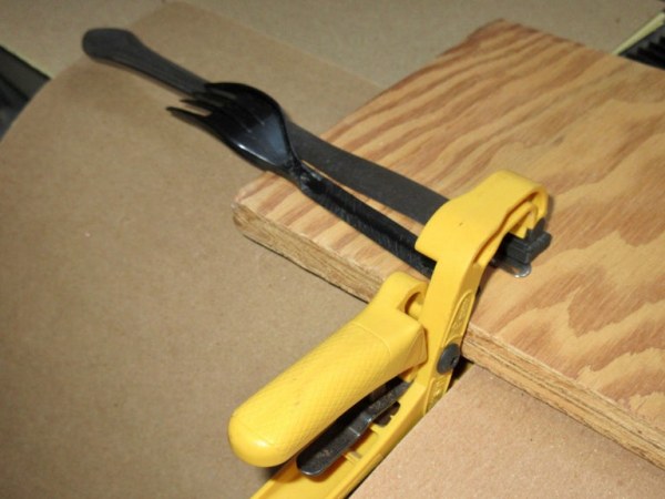
Next, file the handle of the spoon or fork to make it flexible. My fork had a ridge along each side of the handle. To keep the fork steady while filing the ridges off, I clamped a knife to a small wooden board as shown in the photo, and held the fork on the board and against the back of the knife blade while filing. This worked well.
The construction of the mechanism is straightforward, as shown for my unit in the photo.
Step 4: Wiring the Arduino
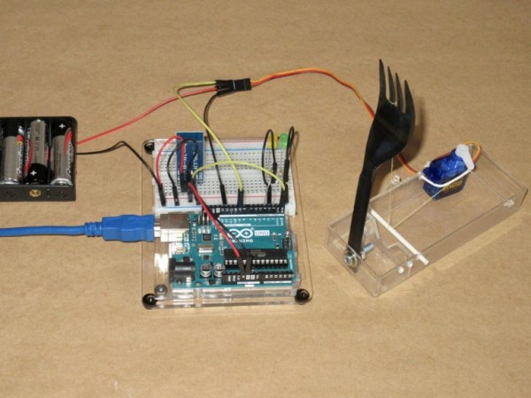
Starting with the circuit after step #11 in Configuring and Pairing the HC-05 (above) the additional wiring should be as described and shown in the photo.
- One wire of a 330 ohm resistor to pin 2 and the other wire to the long wire of the green LED. The short wire of the green LED goes to GND on the breadboard.
- One wire of a 330 ohm resistor to pin 4 and the other wire to the long wire of the yellow LED. The short wire of the yellow LED goes to GND on the breadboard.
- Pin 9 goes to the signal wire of the servo. It’s the yellow one.
- Orange wire of the servo goes to the plus connection of the separate power source.
- Brown wire of the servo goes to GND on the breadboard.
- The minus connection of the separate power source goes to GND on the breadboard.
To double-check, the following parts should be connected to the breadboard’s GND: both LEDs, the servo, the Arduino’s GND, the separate power source, and the HC-05. And the following parts should be connected to the breadboard’s plus power: the Arduino’s +5V and the HC-05.
Step 5: Uploading and Using the Sketch
1. Start the Arduino app on the computer.
2. Connect the Arduino’s USB cable to the computer. The HC-05 should make rapid blinks.
3. Connect the servo’s power wires to a separate power source, and connect the minus of that power source to the Arduino’s or breadboard’s GND.
4. Download the sketch .ino file (located at the very end of this step) or copy the following code and paste it into a new Arduino sketch. (When writing these instructions, the instructables system sometimes dropped part of the #include statement located at the beginning of the code. It should be #include followed by a left arrow < followed by Servo.h followed by a riight arrow >).
//
// LEDs on and servo moving when Attention is high
// December 1, 2020
// Arduino with HC-05 Bluetooth and NeuroSky MindWave Mobile 2
// Yellow LED on when Attn more than 50
// Green LED on when Attn more than 70
// Servo moves 90 degrees when Attn is more than 50
#include<Servo.h>
#define BAUDRATE 57600
#define YLED 4
#define GLED 2
////////// Variables
Servo myservo;
byte payloadData[32] = {0};
byte Attention[5]={0};
byte checksum=0;
byte generatedchecksum=0;
int Plength,Temp;
int Att_Avg=0;
int k=0;
signed int j=0;
////////// Arduino setup
void setup()
{
Serial.begin(BAUDRATE);
pinMode(YLED, OUTPUT);
pinMode(GLED, OUTPUT);
Serial.println(“Average Attention Values”);
myservo.attach(9);
myservo.write(0);
delay(15);
}
////////// Read data
byte ReadOneByte()
{
int ByteRead;
while(!Serial.available());
ByteRead = Serial.read();
return ByteRead;
}
////////// Main program
void loop()
{
////// Look for sync bytes and read data
while (1)
{
if(ReadOneByte() == 170)
{
if(ReadOneByte() == 170)
{
Plength = ReadOneByte();
if(Plength == 32)
{
generatedchecksum = 0;
for(int i = 0; i < Plength; i++)
{
payloadData[i] = ReadOneByte();
generatedchecksum += payloadData[i] ;
}
generatedchecksum = 255 – generatedchecksum;
checksum = ReadOneByte();
////// Obtain Attention data and calculate an average
if(checksum == generatedchecksum)
{
if (payloadData[28]==4)
{
if (j<4)
{
Attention [k] = payloadData[29];
Temp += Attention [k];
j++;
}
else
{
Att_Avg = Temp/4;
////// Display average Attention in Serial Monitor, move servo, and light LEDs
Serial.println(Att_Avg, DEC);
// The next 2 statements would move the servo based on average Attention level.
// Attention level is between 0 and 100, moving servo between 0 and 100 degrees.
// But they are now comments because I decided to move the servo 90 degrees
// when average Attention is higher than 50.
// myservo.write(Att_Avg);
// delay(15);
if (Att_Avg>50)
{
digitalWrite(YLED, HIGH);
myservo.write(90);
delay(15);
}
else
{
digitalWrite(YLED, LOW);
myservo.write(0);
delay(15); }
if(Att_Avg>70)
{
digitalWrite(GLED, HIGH);
}
else
{
digitalWrite(GLED, LOW);
}
j=0;
Temp=0;
}
}
}
}
}
}
}
}
5. Disconnect the HC-05’s TXD wire from the Arduino’s RX (pin 0), upload the sketch, and reconnect this RX wire.
6. Open the Serial Monitor. Check that the baud rate is 57600.
7. Power-on the MindWave. After a few seconds the HC-05 should make 2 quick blinks every 3-4 seconds, indicating the devices are paired.
8. Put the MindWave on your head. It should now send data to the Arduino. The Serial Monitor should show the Attention level every few seconds, the yellow LED should turn on and the fork bend when Attention is more than 50, and the green LED turn on when Attention is more than 70.
9. When finished, close the Serial Monitor.
10. Power-off the MindWave.
11. Disconnect the USB cable from the Arduino or the computer.
12. Quit the Arduino app.
13. Disconnect the servo’s power wires from the separate power source.
Maximizing the Attention Level
Ways to maximize the Attention level vary for different people. Here are some suggestions:
- Concentrate on reading the list of ingredients on a food container.
- Memorize some nutrition facts on a food container.
- Count backwards.
- Do arithmetic operations in your head.
- Listen to a rap song and try to understand the words.
- Read something in a language you’re not fluent in.
Important Notes
- If your HC-05’s firmware is version 2 or 3, my understanding is that the command AT+INIT is needed before the AT+INQ command. My HC-05’s firmware is version 4.0-20190815, and the AT+INIT command was not recognized. To check your HC-05’s version, type this command: AT+VERSION
- If you press Arduino’s Reset button, this restores the HC-05‘s settings to the factory defaults. All the pairing steps will have to be repeated.
- If the HC-05’s TXD is not disconnected from the Arduino’s RX before a sketch is uploaded, an error message will appear at the bottom of the Arduino app’s window on the computer screen. The following error message is repeated 10 times: avrdude: stk500_recv(): programmer is not responding avrdude: stk500_getsync() attempt 1 of 10: not in sync: resp=0x00
- If using a servo, it needs a separate power source such as 3 1.5 volt batteries. The GND of the Arduino must be connected to the minus of the external power source. Without external power, there seems to be insufficient power from the USB source and the HC-05 loses its pairing when the servo activates. It pairs after a few seconds and then unpairs next time the servo activates.
Future Enhancements
When I researched NeuroSky projects on the Internet, it was interesting to see which signals the developers chose to use in their projects. Most projects used only Attention and a few also utilized Meditation and/or Blinking.
I plan to experiment with these other signals to control a robot vehicle or a drone.
Source: Brainwaves Bend a Fork