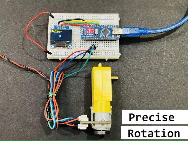
Summary of BO Motor With Encoder Gives Precise Movement
Summary: The article explains integrating a magnetic quadrature encoder with a geared BO DC motor to achieve precise speed and direction feedback for projects using PID or microcontroller control. It describes encoder operation, wiring to Arduino interrupt pins, pulse calculation (8 pulses × 120:1 gear = 960 PPR), sample Arduino code for counting pulses and computing velocity, a compatible Hall-sensor circuit, power considerations, and testing results at 5 V.
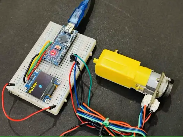
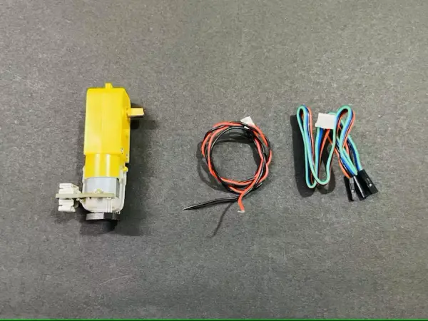
Parts used in the BO motor encoder project:
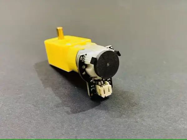
- DF Robot geared BO DC motor with built-in quadrature encoder (gear ratio 120:1)
- Magnetic rotary encoder (embedded quadrature encoder, 8 pulses per motor rev)
- Arduino (custom DIY Arduino board used)
- Hall effect sensors (two, as shown in circuit)
- Resistors (for level shifting and overcurrent protection)
- Motor driver (implicit for driving motor via microcontroller)
- Power supply (4.5–7.5V for encoder; suitable voltage for motor, tested at 5V)
- Wiring and connectors (for encoder A/B, power, and microcontroller pins)
- OLED display (Adafruit SSD1306 used in velocity example)
- Optional PCB and components (JLCPCB for PCB/PCBA or manual soldering)
For precise BO motor control or for crafting budget-friendly projects utilizing PID, the integration of such encoders with motors holds great promise.
Story
Geared DC motors find extensive application in hobby projects, such as constructing robotic cars and moving robotics. Yet, for meticulous movement, the utilization of specialized motors becomes paramount. Take the case of a balancing robot, where stepper motors are essential to achieve the requisite wheel stepping accuracy. The intricate movement demands of balance cannot be adequately met by standard motors. However, there exists a solution to this quandary: when the need for precision movement arises without resorting to stepper motors, encoders can be seamlessly integrated with BO motors.
This encoder solely captures the rotational speed and direction, subsequently translating them into pulses that can be harmonized with a microcontroller and driver. This synchronization facilitates the precise modulation of voltage levels in accordance with the requisite pulses. These controlled pulses ultimately govern the motor’s movement speed, making the utilization of BO motors an economically efficient resolution.
How magnetic encoder works:
An electronic magnetic rotary encoder employs magnetic fields for gauging the rotation of an object. This mechanism comprises a magnetized rotor alongside a stationary sensor. When the rotor undergoes rotation, the sensor identifies alterations in the magnetic field and subsequently translates them into electrical signals.
These signals undergo processing to ascertain crucial aspects like the object’s rotational position, speed, and direction. The sensor’s foundation can draw upon diverse technologies like Hall effect sensors or magneto-resistive sensors, designed to identify fluctuations in the magnetic field. Through meticulous analysis of these signals, the encoder delivers precise rotational data, rendering it indispensable for motor control, robotics, and industrial automation applications.
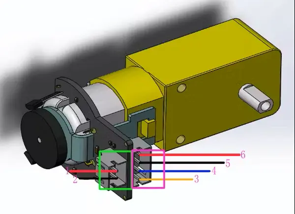
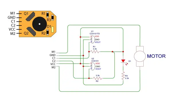
A basic encoder comprises four wires (two for power supply, one for interrupt, and another for rotation direction). In this setup, the microcontroller doesn’t actively monitor encoder motion; instead, the encoder autonomously generates an interrupt signal that notifies the microcontroller, thereby recording each step.
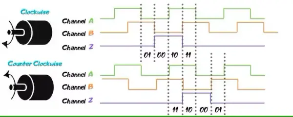
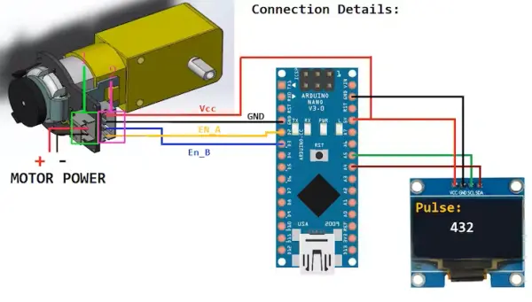
Motor Encoder A, denoted as C1 with PinA, establishes a link with Arduino’s pin 2. Arduino’s pin 2 serves to log instances of rising digital signals stemming from Encoder A.
As for Motor Encoder B, identified as C2 with PinB, it interfaces with Arduino’s pin 3. The signal gleaned from Arduino’s pin 3 determines the motor’s direction, indicating either forward or reverse movement.
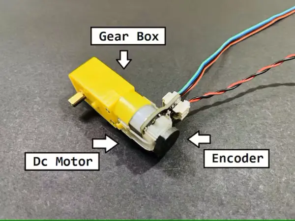
Gear motor and Encoder Specs:
Presently, I possess a BO motor sourced from DF Robot. This motor is equipped with gearing, sporting a gear ratio of 120:1 (translating to one output shaft movement for every 120 motor rotations). An embedded quadrature encoder accompanies the motor, furnishing a resolution of 8 pulses per round, thus yielding a peak output of 960 pulses within a single rotation.
- Gear ratio: 120:1
- No-load speed @ 6V: 160 rpm
- No-load speed @ 3V: 60 rpm
- No-load current @ 6V: 0.17A
- No-load current @ 3V: 0.14A
- Max Stall current: 2.8A
- Max Stall torque: 0.8kgf.cm
- Rated torque: 0.2kgf.cm
- Encoder operating voltage: 4.5 to 7.5V
Encoder Value Computation:
Pulses per revolution for the encoder = 8
A single rotation of the output shaft = Pulses per revolution for the encoder × Gear Ratio
Hence, pulses per one rotation = 8 × 120 = 960 pulses per revolution.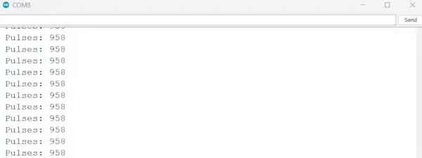
Code for Pulse Calculation:
// Encoder output to Arduino Interrupt pin. Tracks the pulse count.
#define encoder0PinA 2

// Keep track of the number of right wheel pulses
volatile long right_wheel_pulse_count = 0;

void setup() {

  // Open the serial port at 9600 bps
  Serial.begin(9600);

  // Set pin states of the encoder
  pinMode(encoder0PinA , INPUT_PULLUP);

  // Every time the pin goes high, this is a pulse
  attachInterrupt(digitalPinToInterrupt(encoder0PinA), right_wheel_pulse, RISING);
  // 2Nd method to use Interuppt pin (Either use PIN 0 or use funtion digitalPinToInterrupt
}

void loop() {

    Serial.print(" Pulses: ");
    Serial.println(right_wheel_pulse_count);
}

// Increment the number of pulses by 1
void right_wheel_pulse() {
  right_wheel_pulse_count++;
}
Code for Velocity of motor:
This code resets the encoder counter following each rotation, providing an accurate count of motor revolutions per unit of time.
//The sample code for driving one way motor encoder
#include <Wire.h>
#include <Adafruit_GFX.h>
#include <Adafruit_SSD1306.h>

#define OLED_RESET 1
Adafruit_SSD1306 display(128, 64, &Wire, OLED_RESET);
const byte encoder0pinA = 2; //A pin -> the interrupt pin 0
const byte encoder0pinB = 3; //B pin -> the digital pin 3
byte encoder0PinALast;       //Store the previous state of pin

int duration;     //the number of the pulses
boolean Direction;//the rotation direction


void setup()
{
  Serial.begin(9600);//Initialize the serial port
  EncoderInit();     //Initialize function for encoder
  Wire.begin();
  display.begin(SSD1306_SWITCHCAPVCC, 0x3C);
  display.clearDisplay();
}

void loop()
{
  Serial.print("Pulse:");
  Serial.println(duration);

  display.clearDisplay();
  display.setTextSize(2);
  display.setTextColor(WHITE);
  display.setCursor(0,0);
  display.print("Pulse:");
  display.display();

  display.setTextSize(2);
  display.setTextColor(WHITE);
  display.setCursor(50,30);
  display.print(duration/2);
  display.display();
  duration=0;
  delay(300);

}

void EncoderInit()
{
  Direction = true;   //default -> Forward
  pinMode(encoder0pinB,INPUT);
  attachInterrupt(0, wheelSpeed, CHANGE); // digitalPinToInterrupt(interruptPin) instead of 0
// syntax of interrupt will be = interrupt pin, function to be executed, Condition of Function HIGH, LOW, CHANGE, RISING AND FALLING
}

void wheelSpeed()
{
  int Nstate = digitalRead(encoder0pinA);
  if((encoder0PinALast == LOW) && Nstate==HIGH)
  {
    int val = digitalRead(encoder0pinB);
    if(val == LOW && Direction)
    {
      Direction = false; //Reverse
    }
    else if(val == HIGH && !Direction)
    {
      Direction = true;  //Forward
    }
  }
  encoder0PinALast = Nstate;

  if(!Direction)  duration++;
  else  duration--;
}
Circuit:
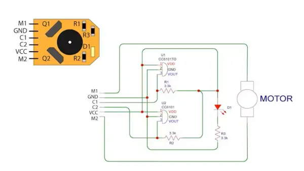
I discovered a compatible circuit configuration for the encoder design, which inherently outlines the pragmatic methodology. Within it, two Hall effect sensors are visible, serving to quantify alterations in the magnetic field corresponding to motion. The sensor’s output interfaces with the microcontroller’s interrupt pin. Incorporating resistors serves two purposes: aligning transistor levels and providing safeguarding against overcurrent.
Both the motor and encoder can draw power from a shared source, but it’s crucial to bear in mind the upper limits of voltage readings. Additionally, the motor can function autonomously without the encoder. In this scenario, simply connect the motor wires to the power supply, and it will operate as a standard unit.
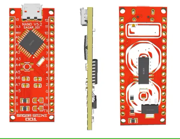
My Arduino:
Presenting my self-designed Arduino board, with a more recent version having been recently released. This fully compatible DIY board offers enhanced functionality.
JLCPCB, headquartered in China, specializes in the production of PCB, PCBA, stencils, 3D printing, SMT assembly, and metal CNC services. You have the option to manually solder the PCB by arranging the components or you can opt for a pre-assembled PCB with all components from JLCPCB. If you decide to undertake the assembly yourself, a majority of the required components are accessible online. You can refer to the Bill of Materials (BOM) file provided in the download folder for further guidance.
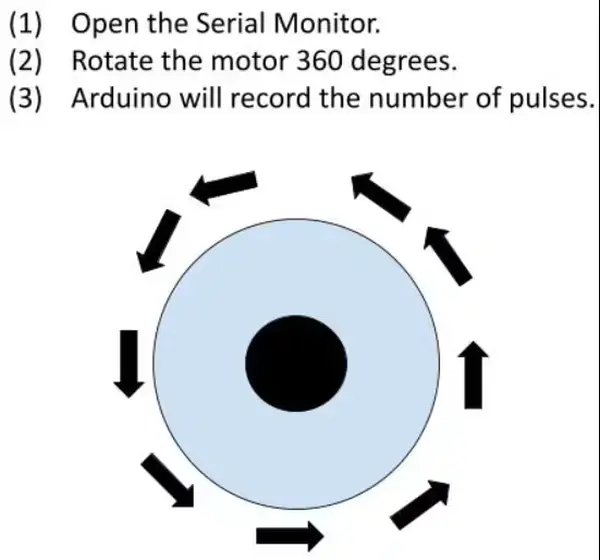
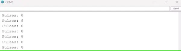
Testing:
I’ve uploaded the velocity code, which yields the pulse count relative to the motor’s speed. The code incorporates an automatic encoder value reset every 0.3 seconds. It’s important to note that the motor’s speed and subsequently the pulse count are contingent on the operating voltage. My DC motor was operated at 5 volts, and the results are depicted in the accompanying image.
Schematics
Code
//The sample code for driving one way motor encoder
#include <Wire.h>
#include <Adafruit_GFX.h>
#include <Adafruit_SSD1306.h>

#define OLED_RESET 1
Adafruit_SSD1306 display(128, 64, &Wire, OLED_RESET);
const byte encoder0pinA = 2; //A pin -> the interrupt pin 0
const byte encoder0pinB = 3; //B pin -> the digital pin 3
byte encoder0PinALast;       //Store the previous state of pin

int duration;     //the number of the pulses
boolean Direction;//the rotation direction


void setup()
{
  Serial.begin(9600);//Initialize the serial port
  EncoderInit();     //Initialize function for encoder
  Wire.begin();
  display.begin(SSD1306_SWITCHCAPVCC, 0x3C);
  display.clearDisplay();
}

void loop()
{
  Serial.print("Pulse:");
  Serial.println(duration);

  display.clearDisplay();
  display.setTextSize(2);
  display.setTextColor(WHITE);
  display.setCursor(0,0);
  display.print("Pulse:");
  display.display();

  display.setTextSize(2);
  display.setTextColor(WHITE);
  display.setCursor(50,30);
  display.print(duration/2);
  display.display();
  duration=0;
  delay(300);

}

void EncoderInit()
{
  Direction = true;   //default -> Forward
  pinMode(encoder0pinB,INPUT);
  attachInterrupt(0, wheelSpeed, CHANGE); // digitalPinToInterrupt(interruptPin) instead of 0
// syntax of interrupt will be = interrupt pin, function to be executed, Condition of Function HIGH, LOW, CHNAGE, RISING AND FALLING
}

void wheelSpeed()
{
  int Nstate = digitalRead(encoder0pinA);
  if((encoder0PinALast == LOW) && Nstate==HIGH)
  {
    int val = digitalRead(encoder0pinB);
    if(val == LOW && Direction)
    {
      Direction = false; //Reverse
    }
    else if(val == HIGH && !Direction)
    {
      Direction = true;  //Forward
    }
  }
  encoder0PinALast = Nstate;

  if(!Direction)  duration++;
  else  duration--;
}
- What encoder resolution does the DF Robot BO motor provide?
The motor has an encoder with 8 pulses per motor revolution, and with a 120:1 gear ratio this yields 960 pulses per output shaft revolution. - How is the encoder connected to the Arduino?
Encoder A (PinA) connects to Arduino pin 2 (interrupt) and Encoder B (PinB) connects to Arduino pin 3 to determine direction. - Can the motor and encoder share the same power source?
Yes, both can draw power from a shared source while observing the encoder operating voltage limits. - How does the magnetic encoder detect rotation?
It uses a magnetized rotor and stationary sensors (Hall effect or magneto-resistive) to detect magnetic field changes and output electrical signals for position, speed, and direction. - How are pulses counted in the provided code?
The code uses an interrupt on the encoder A pin to increment a volatile pulse counter each rising edge and prints the count over serial. - How is motor direction determined in the velocity code?
The code reads encoder A and B states; transitions and the B pin state toggle a Direction boolean to track forward or reverse rotation. - What is the encoder operating voltage range?
The encoder operates between 4.5 and 7.5 volts according to the article. - Does the motor work without the encoder?
Yes, the motor can run independently by connecting its wires to the power supply without the encoder. - How often does the example velocity code reset the encoder count?
The velocity example resets the duration counter every 0.3 seconds (delay 300 ms) for pulse-per-time measurements.