
Summary of AT89C2051 Development Stick
The AT89C2051 Development Stick is a compact SIMM-style module designed for interfacing with 89C2051-compatible microcontrollers. It features an onboard voltage regulator, reset switch, power LED, and access to all I/O pins via a 20-pin Berg connector. The board includes a crystal oscillator, EEPROM for data storage, and mounting holes, making it ideal as a plug-in daughter card for various projects.
Parts used in the AT89C2051 Development Stick:
- AT89C2051 compatible MCU
- Voltage regulator (U2)
- RESET switch
- 11.0592 MHz Crystal (Y1)
- 4K external EEPROM (24C04, U3)
- Power-On LED (D1)
- 20-Pin Berg connector (J1)
- 20-Pin IC socket
- Mounting holes (3.2 mm)
- Resistors R4 and R5
- Capacitors C2, C3, and C6
AT89C2051_DEV_STICK_PIC
89C2051 Development Stick kit offers an easy way of interfacing 89C2051 compatible MCU’s.
Slim design with plug in type approach
Voltage regulator on board for stable and regulated supply to the MCU
RESET switch for resetting the MCU
0592 MHz Crystal
4K external EEPROM
Power-On LED for indicator
20-Pin well marked Berg connector for ease of connection
Access to all IO pins & supply pin on the Berg connector
20-Pin IC socket for MCU
Four mounting holes of 3.2 mm each
PCB dimensions 35 mm x 72 mm
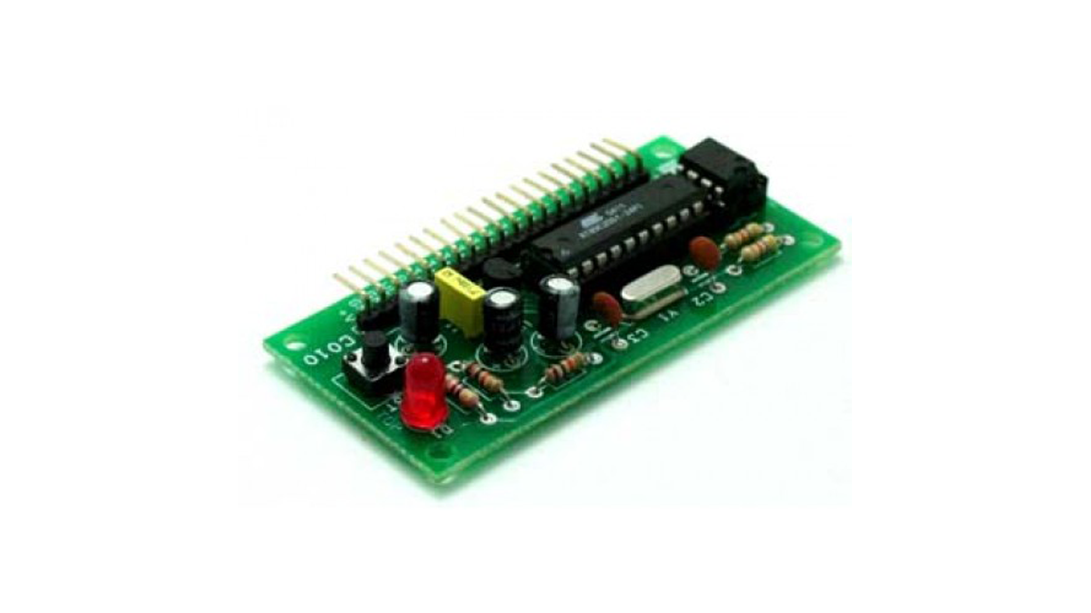
This is a development board made available in form of a SIMM fashion module for your project. This board accepts all compatible MCUs to the 89C2051 from ATMEL.
This board can be used as a plug-in daughter card in your project with all the IO pins of the MCU coming out.
Power input to the board is applied at Pin #1 and #2
Regulated power is available at Pin# 4 of Connector J1
An Onboard Reset Switch offers a easy way to reset the Microcontroller
LED D1 indicates power on board
Optionally, a 24C04 EEPROM on the module can help you store valuable data on it for your project
If you don’t wish to use the EEPROM you can omit to assemble R4, R5 and U3
If you plan to power this module from your Project PCB then you can omit to assemble U2, C6
Crystal supplied with this kit is 11.0592 MHz. If you intend to use other frequency crystal, please replace Y1, C2 and C3 components as per specification mentioned in the data sheet of the Microcontroller
For More Details: AT89C2051 Development Stick
- How do you power the development stick?
Power input is applied at Pin #1 and #2 of the connector. - Where can regulated power be found on the board?
Regulated power is available at Pin# 4 of Connector J1. - What component resets the microcontroller?
An Onboard Reset Switch offers an easy way to reset the Microcontroller. - Which LED indicates that the board is powered on?
LED D1 indicates power on board. - Can the EEPROM be omitted from the assembly?
If you do not wish to use the EEPROM, you can omit assembling R4, R5, and U3. - What components should be skipped if powering from a Project PCB?
You can omit assembling U2 and C6 if you plan to power this module from your Project PCB. - What frequency crystal is supplied with this kit?
The crystal supplied with this kit is 11.0592 MHz. - How do you change the crystal frequency?
To use other frequency crystals, replace Y1, C2, and C3 components as per the Microcontroller data sheet. - Does the board support different types of MCUs?
This board accepts all compatible MCUs to the 89C2051 from ATMEL. - What are the dimensions of the PCB?
PCB dimensions are 35 mm x 72 mm.
