Summary of Arduino Powered Micro Quadruped
This article details the design and assembly of a compact, robust Arduino-powered micro quadruped robot. Built using 3D printing and hobby electronics, the project aims for small size and versatility to test various walking gaits. The author emphasizes using high-quality servo motors to prevent failure during dynamic motion experiments. The guide covers CAD design in Fusion 360, part fabrication, mechanical assembly, wiring with an Arduino Uno and sensor shield, and programming inverse kinematics for smooth locomotion.
Parts used in the Arduino Powered Micro Quadruped:
- Arduino Uno
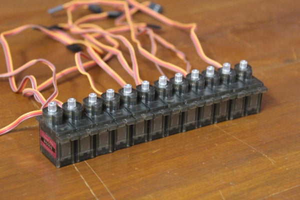
- Towerpro MG90s micro servo motor (12 units)
- Arduino Sensor Shield V5
- 3D printer filament
- 3D printer
- Screws
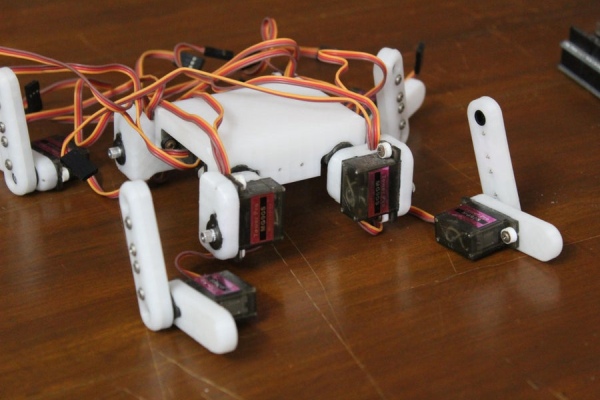
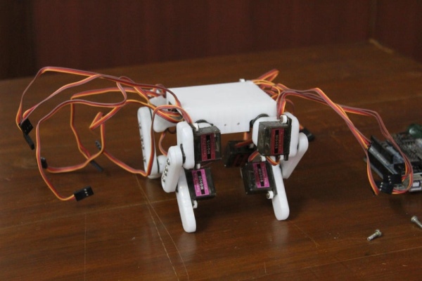
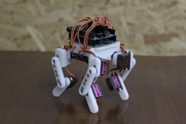
From the previous projects on this page, you can probably see that I have a deep interest in robotic projects. In one of my previous Instructables, I built a quadruped robot using large heavy-duty servo motors, and this time I decided to try and make a micro version of the quadruped robot that is significantly more versatile and nimble. In this Instructable, I will show you the design and assembly of the robotic micro quadruped.
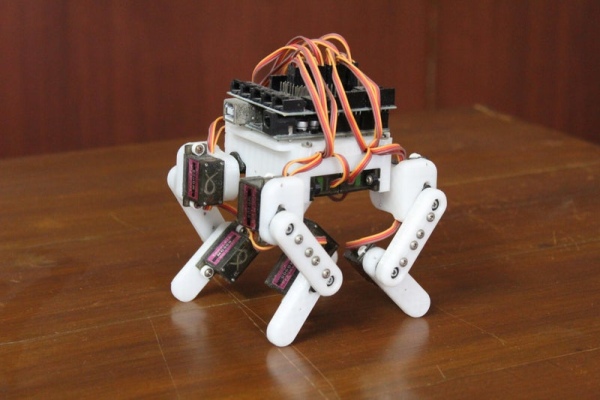
The primary goal while building this project was to make the system as small as possible while being robust so that while experimenting with various walking and running gaits I wouldn’t have to constantly worry about the hardware failing. This allowed me to push the hardware to its limit and experiment with complex gaits and motions. A secondary goal was to make the quadruped relatively low-cost using readily available hobby parts and 3D printing which allowed for rapid prototyping. These two goals combined provide a robust foundation to perform various experiments, letting one develop the quadruped for more specific requirements such as navigation, obstacle avoidance, and dynamic locomotion.
Follow on to create your own Arduino Powered Micro Quadruped and do drop a favorite and follow this page if you enjoyed the project and decide to build your own version. I would love to see your own versions so do post your creations using the “I made it” section.
Step 1: Overview and Design Process
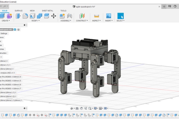
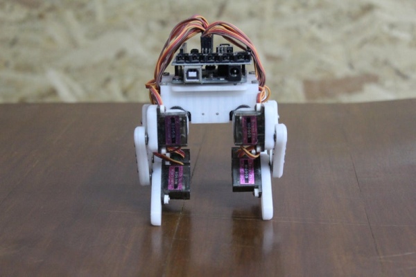
The quadruped was designed in Autodesk’s free-to-use Fusion 360 3d modelling software. I began by importing the micro servo motors into the design and built the legs and body around them. The design was made with simplicity and robustness in mind since I hoped to experiment with various dynamic gaits that would push the hardware to its limits. Another goal while designing the quadruped was to keep the model as compact as possible to make maximum use of the torque provided by the servo motors. The dimensions of the links were made to achieve a large range of motion while minimizing the overall length. Making them too short would make the 3D printed parts collide, reducing the range of motion, and making it too long would exert unnecessary torque on the actuators. Finally, I designed the body of the robot onto which the Arduino and other electronic components would mount. I have also left additional mounting points on the top panel of the body to accommodate other sensors and instruments and making the project scalable for further improvements. One could add sensors such as distance sensors, cameras or other actuated mechanisms such as robotic grippers.
Note: The parts are included in one of the following steps.
Step 2: Materials Needed
Here is the list of all the components and parts required to make your very own Arduino Powered Micro Quadruped. All parts should be commonly available and easy to find in local hardware shops or online.
ELECTRONICS:
- Arduino Uno x 1
- Towerpro MG90s micro servo motor x 12
- Arduino Sensor Shield (I recommend the V5 version but I had the V4 version)
HARDWARE:
- 3D printer filament (in case you don’t own a 3D printer, there should be a 3D printer in a local workspace or the prints can be done online for quite cheap)
TOOLS:
- 3D printer
The most significant cost of this project is the 12 servo motors. I recommend going for the mid-range to high-range version instead of using the cheap ones with plastic gears since they tend to break easily. Excluding the tools, the total cost of this project is approximately 60$.
Step 3: Power of the Arduino
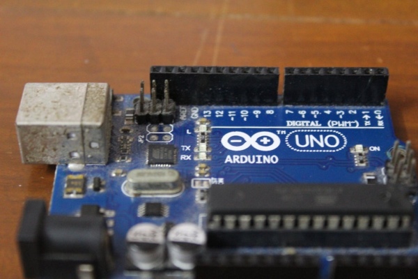
An Arduino Uno was used in this project. The Arduino was responsible to compute the motion paths of the various gaits that were tested and instructed the actuators to move to precise angles at precise speeds to create a smooth walking motion. An Arduino is a great choice for developing projects because of its versatility. It provides a bunch of IO pins and also provides communication interfaces such as serial, I2C, and SPI to communicate with other microcontrollers and sensors. The Arduino also provides a great platform for rapid prototyping and testing and also gives developers room for improvements and expandability. In this project, further versions will include an Inertial Measurement Unit for motion processing such as fall detection and dynamic locomotion on uneven terrain and a distance measuring sensor to avoid obstacles.
The Arduino IDE was used for this project. (Arduino also provides a web-based IDE)
Note: The programs for the robot can be downloaded from one of the following steps.
Step 4: Digitally Fabricated Parts
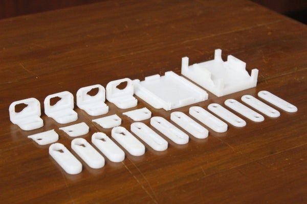
The parts required for this project had to be custom designed therefore a 3D printer was used to print them out. The prints were made at 40% infill, 2 perimeters, 0.4mm nozzle, and a layer height of 0.1mm with PLA, color of your choice. Below you can find the complete list of parts and the STLs to print your own version.
Note: From here on the parts will be referred to using the names in the list.
- leg1 x 4
- leg2 x 4
- leg2 cover x 4
- leg3 x 2
- leg3 cover x 2
- leg3 mirror x 2
- leg3 mirror cover x 2
- body x 1
- wire cover x 1
- servo horn spacer x 24 (optional, if your screws are too long)
In total, excluding the spacers, there are 22 parts. The total printing time is about 20 hours.
Step 5: Preparing the Links
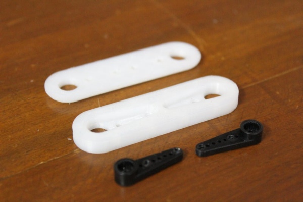
Begin making the links by pushing the servo horns into the slots on the leg2 piece and using screws to attach the horns in place along with the leg2 cover. Next, push a micro servo motor into the dedicated slot on the leg1 piece and attach the motor firmly using two more screws.
Repeat this process with the rest of the 3 legs.
Step 6: Assembling the Legs
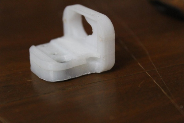
Next, push a servo horn into each of the leg3 and leg3 mirror pieces. Before securing the horn with screws along with the cover, pass the wires of the servo motor attached to the leg1 piece and an additional servo through the wire management slot between the leg3 piece and the leg3 cover piece. Screw the leg3 cover onto the leg3 piece using two screws and push the second servo into the slot on the leg3 piece and finally fasten the second servo with two more screws.
Repeat this process for the rest of the legs.
Step 7: Assembling the Body
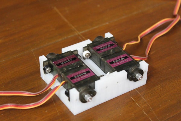
Mount 4 servo motors to the body using screws from the inside. Although it may be a bit tricky to mount the servos with screws from the inside, it is crucial because screws attached from the outside would interfere with the legs and reduce the range of motion of each leg.
Step 8: Putting It All Together
Attach the 4 leg3 pieces to each of the 4 servos on the body and use the leg2 link to join the second servo with the first servo connected to the leg1 link.
Repeat this process for the other 3 legs and with that the general assembly of your micro quadruped robot is ready.
Step 9: Wire Management and Circuit
I decided to use a sensor shield that provided connections for servo motors. I would recommend that you use the sensor shield v5 since it features an onboard external power supply port. However, the one that I used did not have this option. Looking at the sensor shield more closely, I noticed that the sensor shield was drawing power from the Arduino’s onboard 5v pin (which is a terrible idea when it comes to high power servo motors since you risk damaging the Arduino). The fix to this problem was to bend the 5v pin on the sensor shield out of the way so that it would not connect to the 5v pin of the Arduino. In this way, we can now provide external power through the 5v pin without damaging the Arduino.
Begin by passing the wires through the body so that there are no extra wires hanging loose. Next, connect the servo ports to the sensor shield. The connections of the signal pins of the 12 servo motors are indicated in the table below.
Note: Hip1Servo refers to the servo attached to the body. Hip2Servo refers to the servo attached to the leg.
Leg 1 (forward left):
- Hip1Servo >> 7
- Hip2Servo >> 6
- KneeServo >> 5
Leg 2 (forward right):
- Hip1Servo >> 4
- Hip2Servo >> 3
- KneeServo >> 2
Leg 3 (back left):
- Hip1Servo >> 13
- Hip2Servo >> 12
- KneeServo >> 11
Leg 4 (back right):
- Hip1Servo >> 10
- Hip2Servo >> 8
- KneeServo >> 9
Step 10: Initial Setup
Before beginning to program complex gaits and other movements, we need to set up the zero points of each servo. This gives the robot a reference point which it uses to perform various movements.
To avoid damages to the robot you can remove the servo horn links.
- Begin by cloning the micro quadruped program from the following GitHub repo: https://github.com/kousheekc/Micro-Quadruped-Robot
- Uncomment the 8th line of the main.ino file and comment out the rest of the lines in the setup and loop
- Upload the file to the Arduino
This code places each of the servos at 90 degrees. Once the servos have reached the 90-degree position you can reattach the links such that the legs are perfectly straight and the servo attached to the body is perpendicular to the top panel of the quadruped.
At this point, because of the design of the servo horns, some of the joints may still not be perfectly straight. The solution to this is to adjust the zero_positions array found on the 13th line of the Quadruped.h file. Each number represents the zero position of the corresponding servo (the order is the same as the order in which you attached the servo to the Arduino). Tweak these values a bit till the legs are perfectly straight.
Note: Here are the values that I use although these values may not work for you:
int zero_positions[12] = {83, 89, 164, 85, 93, 3, 102, 90, 15, 90, 99, 175};
Also, note that this program can work with any quadruped that you build. Simply change the values in the constructor called on line 3 of main.ino. (More details can be found in the readme on the GitHub page)
Step 11: Brief Introduction to Kinematics
To make the quadruped perform useful actions such as running, walking, and other movements the servos need to be programmed in the form of motion paths. Motion paths are paths along which the end effector (the feet in this case) travel along. There are two ways of achieving this:
- One approach would be to feed the joint angles of the various motors in a brute force manner. This approach can be time-consuming, tedious, and also filled with errors since the judgment is purely visual. Instead, there is a smarter way of achieving the desired results.
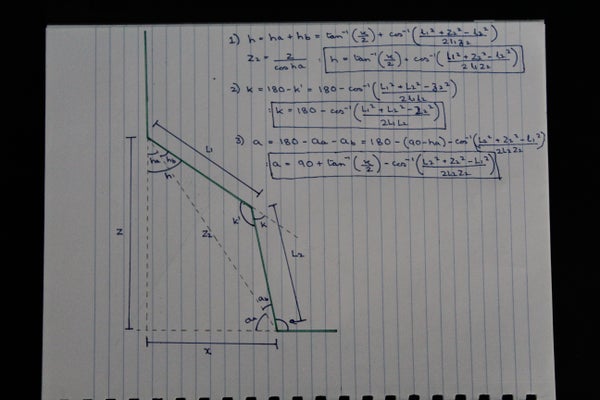
- The second approach revolves around feeding the coordinates of the end effector instead of all the joint angles. This is what is known as Inverse Kinematics. The user inputs coordinates and the joint angles adjust to position the end effector at the specified coordinates. This method can be considered as a black box that takes as inputs a coordinate and outputs the joint angles. Those who are interested in how the trigonometric equations of this black box were developed can look at the diagram above. For those who are not interested, the equations are already programmed and can be used using the pos function which takes as input x, y, z, which is the cartesian location of the end effector and outputs three angles corresponding to the motors.
The program containing these functions can be found in the next step.
Step 12: Programming the Quadruped

Once the wiring and initialization are complete, you can program the robot and generate cool motion paths so that the robot performs interesting tasks. After uploading the program, the robot should begin to walk. You can vary the parameters of the gait by using the various methods included in the robot class.
Step 13: Final Results
The quadruped robot can take steps that vary from 4 to 1 cm long. The speed too can be varied while keeping the gait balanced. This quadruped provides a robust platform to experiment with various other gaits and other objectives such as jumping or complete tasks. I would recommend you try to change the motion paths of the legs to create your own gaits and discover how various gaits affect the performance of the robot. I have also left multiple mounting points at the top of the robot for additional sensors such as distance measuring sensors for obstacle avoidance tasks or IMU for dynamic gaits on uneven terrain. One could also experiment with an additional gripper arm mounted to the top of the robot since the robot is extremely stable and robust and won’t tip over easily.
Hope you enjoyed this Instructable and it has inspired you to build your own, and do share your own versions in the “I made it” section”. Apart from that, feedback, questions, comment, concerns can be addressed in the comment section below.
Source: Arduino Powered Micro Quadruped
- How was the robot designed?
The quadruped was designed in Autodesk's free-to-use Fusion 360 3d modelling software. - What is the primary goal of building this project?
The primary goal was to make the system as small as possible while being robust to allow hardware experimentation without constant worry about failure. - Which servo motors are recommended for this build?
The author recommends mid-range to high-range versions like the Towerpro MG90s instead of cheap ones with plastic gears because they tend to break easily. - How should the servos be mounted to the body?
Servos must be mounted to the body using screws from the inside so that external screws do not interfere with the legs or reduce their range of motion. - Why is the 5v pin on the sensor shield modified?
The 5v pin is bent out of the way to prevent the shield from drawing power from the Arduino, which risks damaging the board when powering high-power servo motors. - What method is used to control leg movement?
Inverse Kinematics is used, where the user inputs coordinates for the end effector, and the program outputs the necessary joint angles. - How do you set the zero points for the servos?
You upload a specific program to place servos at 90 degrees, reattach links for straight legs, and then tweak the zero_positions array in the code until joints are perfectly aligned. - Can additional sensors be added to this robot?
Yes, additional mounting points on the top panel allow for adding distance sensors, cameras, IMUs, or robotic grippers.