Summary of Arduino Nano Tutorial – Pinout & Schematics
The article explains the Arduino Nano board, comparing it to the UNO, detailing its ATmega328P specs, and providing a full pinout description including digital, analog, power, SPI/ICSP, reset, and special-function pins. It lists pin functions, PWM, serial, I2C, ADC, and ICSP usage for programming and notes Nano’s mini-USB power/programming port and additional ADC pins.
Parts used in theArduino Nano Pinout:
- Arduino Nano board (ATmega328P)
- FTDI USB-to-TTL Serial chip (implied for USB interface and 3V3 output)
- Breadboard (implied for connections)
- USB mini cable (for programming and serial monitor)
- On-board voltage regulator (for +5V output)
- ICSP header (MISO, MOSI, SCK, RST, Vcc, GND)
- Reset switch or button (implied for reset pin)
- External power supply (VIN input, 7-12V)
Arduino Nano Pinout
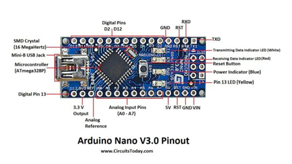
The Arduino Nano is indeed small in size but is packed with all the features of a regular microcontroller and can also be connected to the breadboard. The Nano board proposed herein is approximately 7 grams in weight and 4. 5 cm by 1. 8 cm (length by breadth) Eight centimeters, in length by breadth from the size of the box. This article underscores the type of board under discussion for detailing, that being the Arduino Nano board, with noteworthy emphasis on the pinout and the positions of each pin.
How different is Arduino Nano?
Arduino Nano is Arduino Duemilanove in a different package but they have the same functionality. The Nano has the ATmega328P microcontroller and even the Arduino UNO has the same processor plugged into its board. The primary distinction between the two is that the UNO board comes in PDIP form with 30 pins, whereas the Nano is offered in TQFP with 32 pins. The additional 2 pins on Arduino Nano are used for ADC functions, whereas UNO has 6 ADC ports compared to Nano’s 8 ADC ports. The Nano board lacks a DC power jack like other Arduino boards; instead, it features a mini-USB port. This port serves dual purposes for programming and serial monitoring. The intriguing aspect of Nano is its ability to select the most powerful power source based on its potential difference, while rendering the power source selector jumper useless.
Arduino Nano – Specification
Arduino Nano Pinout Description
Taking this pin-out diagram below as reference, we shall discuss all the functionalities of each and every pin.
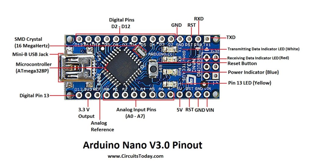
Arduino Nano Pinout
We can infer from the image that Arduino Nano got 36 pins in total. We will see all the pins section wise as well as a detailed format at last.
Digital I/O , PWM - 14 Pins

For Analog Functions - 9 Pins

Power - 7 Pins

SPI (Apart from Digital I/O Section) - 3 Pins

Reset - 3 Pins
______________________________________________________
TOTAL - 36 Pins
Arduino Nano Pin Description
Arduino Nan0 – Pin Description
Pins 1 to 30
| Arduino Nano Pin | Pin Name | Type | Function |
|---|---|---|---|
| 1 | D1/TX | I/O | Digital I/O Pin Serial TX Pin |
| 2 | D0/RX | I/O | Digital I/O Pin Serial RX Pin |
| 3 | RESET | Input | Reset ( Active Low) |
| 4 | GND | Power | Supply Ground |
| 5 | D2 | I/O | Digital I/O Pin |
| 6 | D3 | I/O | Digital I/O Pin |
| 7 | D4 | I/O | Digital I/O Pin |
| 8 | D5 | I/O | Digital I/O Pin |
| 9 | D6 | I/O | Digital I/O Pin |
| 10 | D7 | I/O | Digital I/O Pin |
| 11 | D8 | I/O | Digital I/O Pin |
| 12 | D9 | I/O | Digital I/O Pin |
| 13 | D10 | I/O | Digital I/O Pin |
| 14 | D11 | I/O | Digital I/O Pin |
| 15 | D12 | I/O | Digital I/O Pin |
| 16 | D13 | I/O | Digital I/O Pin |
| 17 | 3V3 | Output | +3.3V Output (from FTDI) |
| 18 | AREF | Input | ADC reference |
| 19 | A0 | Input | Analog Input Channel 0 |
| 20 | A1 | Input | Analog Input Channel 1 |
| 21 | A2 | Input | Analog Input Channel 2 |
| 22 | A3 | Input | Analog Input Channel 3 |
| 23 | A4 | Input | Analog Input Channel 4 |
| 24 | A5 | Input | Analog Input Channel 5 |
| 25 | A6 | Input | Analog Input Channel 6 |
| 26 | A7 | Input | Analog Input Channel 7 |
| 27 | +5V | Output or Input | +5V Output (From On-board Regulator) or +5V (Input from External Power Supply |
| 28 | RESET | Input | Reset ( Active Low) |
| 29 | GND | Power | Supply Ground |
| 30 | VIN | Power | Supply voltage |
ICSP Pins
Arduino Nano Digital Pins
Pins - 1, 2, 5, 6, 7, 8, 9, 10, 11, 12, 13, 14, 15, and 16
As we mentioned earlier, Arduino Nano has fourteen (14) digital I/O pin that can be used as digital input or output pins. The pins work at a.max voltage of 5.0V with 5V being high state and 0V being low state this is in regard to the digital state of the system. Every pin is enabled to supply as well as take in a current of 40mA and features pull-up resistor with a value of between 20/50 k ohms. Although there are only 14 digital pins in the Nano pin, any of these 14 pins can be used as either the input or output depending on the enabling of pinMode(), writing of digitalWrite(), or reading of the digitalRead() function.
In addition to digital input and output functions, digital pins also offer extra features.
Serial Communication Pins
Pins - 1, 2

1 - RX and 2 - TX
These two pins RX- receive and TX- transmit are used for TTL serial data communication. The pins RX and TX are connected to the corresponding pins of the USB-to-TTL Serial chip.
PWM Pins
Pins - 6, 8, 9, 12, 13, and 14
Each of these digital pins provide a Pulse Width Modulation signal of 8-bit resolution. The PWM signal can be generated using analogWrite () function.
External Interrupts
Pins - 5, 6
These pins can be utilized when an external interrupt is required for another processor or controller. These pins can be utilized with the attachInterrupt() function to enable interrupts for INT0 and INT1. These pins can initiate three different types of interrupts: low value interrupt, rising or falling edge interrupt, and change in value interrupt.
SPI Pins
Pins - 13, 14, 15, and 16
If you prefer not to send data asynchronously, you can utilize these Serial Peripheral Interface pins. These pins enable synchronous communication using SCK as the synchronization clock. Despite the fact that the hardware includes this capability, the Arduino software does not come with it as a standard feature. In order to utilize this function, you need to incorporate the SPI Library.
LED
Pin - 16
If you remember your first Arduino code, blinking LED, then you’ll definitely came across this Pin16. The pin 16 is being connected to the blinking LED on the board.
Arduino Nano Analog Pins
Pins - 18, 19, 20, 21, 22, 23, 24, 25, and 26
As previously stated, UNO has 6 analog input pins while Arduino Nano has 8 analog inputs (19 to 26), labeled as A0 through A7. This allows for the connection of 8 analog sensor inputs for processing. Every one of these analog pins includes a built-in ADC with a resolution of 1024 bits, resulting in 1024 possible values. Typically, the pins are gauged starting from ground up to 5V. To set the reference voltage at 0V to 3.3V, you can input 3.3V into the AREF pin (pin 18) using the analogReference() function.
Just like digital pins in Nano, analog pins also have additional functions.
I2C
Pins 23, 24 as A4 and A5
Since SPI communication also has its disadvantages such as 4 essential pins and limited within a device. For long distance communication we use the I2C protocol. I2C supports multi master and multi slave with only two wires. One for clock (SCL) and another for data (SDA). For using this I2C feature we need to import a library called Wire library.
AREF
Pin 18
As mentioned already the AREF- Analog Reference pin is used as a reference voltage for analog input for the ADC conversion.
Reset
Pin 28
Reset pins in Arduino are active LOW pins which means if we make this pin value as LOW i.e., 0v, it will reset the controller. Usually used to be connected with switches to use as reset button.
ICSP

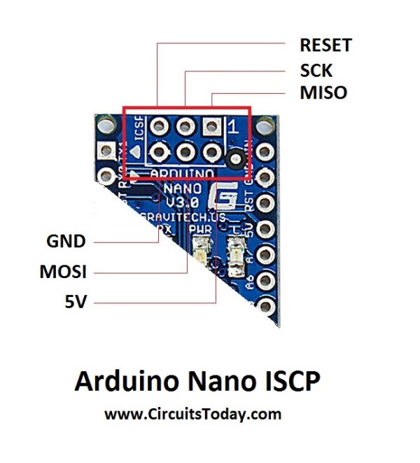
Arduino Nano ICSP
ICSP is an abbreviation for In Circuit Serial Programming and is just one of the many programming methods for Arduino boards. Typically, an Arduino board is programmed using an Arduino bootloader program, however, in the absence or damage of the bootloader, ICSP can be utilized. ICSP is capable of repairing a lost or broken bootloader.
Typically, every ICSP pin is connected to a corresponding Arduino pin with matching name or purpose. In the ICSP header of Nano, MISO is linked to digital pin 12 (Pin 15) whereas MOSI is connected to digital pin 11 (Pin 16) and other pins follow suit. The combination of MISO, MOSI, SCK pins form the majority of an SPI interface.
Using this ICSP, we have the ability to program one Arduino board with another Arduino board.
RESET
Pins 3, 28 and 5 in ICSP
Power
Pins 4, 17, 27, 28, 30 and 2 & 6 in ICSP
Source : Arduino Nano Tutorial – Pinout & Schematics
- How is Arduino Nano different from Arduino UNO?
Arduino Nano uses ATmega328P in TQFP with 32 pins and has 8 ADC ports and a mini-USB instead of UNO's PDIP 30-pin form and DC power jack. - What microcontroller does Arduino Nano use?
The Arduino Nano uses the ATmega328P microcontroller. - How many digital I/O pins does the Arduino Nano have?
The Arduino Nano has 14 digital I/O pins. - Which pins provide PWM on the Arduino Nano?
PWM is available on pins 6, 8, 9, 12, 13, and 14. - How many analog input pins are on the Arduino Nano?
The Arduino Nano has 8 analog input pins labeled A0 through A7 (pins 19 to 26). - Which pins are used for serial communication on the Nano?
Pins 1 (TX) and 2 (RX) are used for TTL serial communication. - What is the function of the ICSP header on the Nano?
The ICSP header provides in-circuit serial programming and connects MISO, MOSI, SCK, RST, Vcc, and GND for programming or SPI usage. - How can I provide reference voltage for ADC on the Nano?
Use the AREF pin (pin 18) to provide the reference voltage for ADC conversions. - What are the power input and output pins on the Nano?
Power pins include VIN (input), +5V (output or input), +3V3 (output from FTDI), and multiple GND pins. - Can the Nano be used as an ISP to program another board?
Yes, the article describes using Arduino as ISP with MOSI, MISO, SCK, Vcc, GND, and D10/Reset connections.