- Masses if not all Arduino Experiments done my way,that being everyone carry’s out experiments different to the next person,as such this instructable will have alot of videos,and pictures as well as detailed descriptions of each experiment what I did how and why….
- LARGE INSTRUCTABLE BE WARNED!
- (there are many arduino instructables on such things,however this will be a very large instructable with many step’s,subject to changes and updates)
Step 1: Part’s Needed.

List and pictures of all parts,tools & Components used in this Instructable… (Any additional spares you have in your electronics box will likely help if your first time making Various Arduino Projects & Tests.)
This huge list of parts and images must seem overwhelming to say the least,but do not worry alot of these are for reference alot of tools can be improvised or scavenged like Switches & LED’s Capacitors Transistors and so on,While others are must have’s such as Solder-less breadboards,arduino boards and accompanying equipment/parts,etc Servos,LCD Screens,Jumper Wires.
Recycling as many parts as you can is advisable to cut down costs on projects,while being green at the same time,solar or alternative power recommended where usable,as most boards can be powered with a couple of rechargeable battery’s.
Step 2: Tool’s Needed (some Optional)
Tools that can help with projects and with making custom parts,as well as testing your recycled (?) components as some may be damaged or not work at all and need disposing of.
Helping hands are most likely the most valuable tool here you will need,for holding wires in place,seeing small writing on parts for there ratings etc,as well as holding solderless breadboards at angles for better visuals of your projects.
Step 3: Skill Level:Basic.(1)
- Bare bones & Basic Starting Projects (Blink & Fade LED Lights And Coding Basics) with Arduino Micro controller’s covered in several Steps.
- Blinking and then Fading A LED light using Timed Delays with a “Digital” Pin,Then using an “Analog” Pin to Control Voltage input (Ability to use basic code Setup,Timed Activation Delays & Voltage Control in analog form)
- Firstly Download Your Arduino IDE (Integrated Development Environment) Used on your PC and downloaded from ,in order to communicate with your Arduino Board Use the following link…….. http://arduino.cc/en/Main/Software download 1.0.5 or the latest version of the IDE (no need to install)
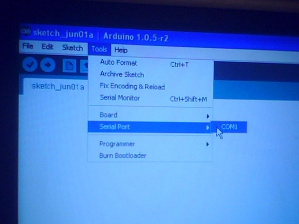
- Connect up your Arduino to you PC via its USB cable,and open the IDE location usually somewhere in Drive C: of your PC’s hard drive (unless you put it elsewhere) Now look at the tools section and find where the “COM” ports are located Remove your Arduino’s USB Cable,and watch which COM port disappeared that is your Arduino,now plug it back in,and set the com port,next pick your Arduino Board from the Board List try not to forget this part when you have switched to mega,micro,nano or any other board variation…………..Next click File “Examples” Basics and then Blink,observe the coding structure,,declaring pin setups with int,void setup,void loop,are primary parts of the coding (CODING AFTER THIS LINE __________________________________)
- /* Blink Turns on an LED on for one second, then off for one second, repeatedly. This example code is in the public domain. */ // Pin 13 has an LED connected on most Arduino boards. // give it a name: int led = 13;// the setup routine runs once when you press reset: void setup() { // initialize the digital pin as an output. pinMode(led, OUTPUT); }// the loop routine runs over and over again forever: void loop() { digitalWrite(led, HIGH); // turn the LED on (HIGH is the voltage level) delay(1000); // wait for a second digitalWrite(led, LOW); // turn the LED off by making the voltage LOW delay(1000); // wait for a second }
- (Copy and paste the above code in part 5 into your IDE or use the example sketch already there) See the primary coding structure and parts and get to know them well for future projects refer back to the basics now and then to relearn forgotten coding or values,the Delay section of the coding is in Milliseconds 1000 being 1second 5000 being 5seconds so on,Digital Pin 13 on the arduino has a built in LED limiting resistor,if you use another pin do not forget to add a 560ohm resistor to stop it burning out in a puff of smoke,Digital Write Function declaring either High/On/ OR Low/Off on the LED with delays on both ends 1second for on 1second for off in the basic sketch.
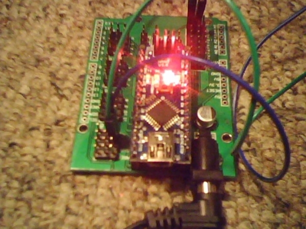
- Set up the circuit connecting an LED +Positive Pin to digital pin 13 and its -Negative Pin to grn (Ground) to complete the circuit to the LED light,using ARDX templates and a solderless breadboard with jumper wires highly recommended.(Watch Videos and see pictures for setup of the circuit and testing)
- SPIN MOTOR SPIN SKETCH (Covered in several steps) ,Using a ARDX Template to make layout of the circuit more easy when attached to a solderless breadboard,parts required are,lots of jumper wires various colours,Transistor TYPE: (P2N2222A) or a variation of this common transistor type,2.2k resistor to be tied to the base/middle transistor pin,blocking diode feedback stop,so current does not flow back into the micro controller and fry it,or the motor itself,(Optional) 220uf capacitor for if the motor does not spin,and needs the power smoothing out on the way to the motor.
- Having done your basic coding in the last Project this will seem much more easy,and more mechanical spinning a motor has many applications from pet toys to robot wheels,same as last time once the circuit has been set up,see pictures and videos,Upload the Code to your IDE Environment CODE After this Line __________________________
- int motorPin = 9; // define the pin the motor is connected to// (if you use pin 9,10,11 or 3you can also control speed)/* * setup() – this function runs once when you turn your Arduino on * We set the motors pin to be an output (turning the pin high (+5v) or low (ground) (-)) * rather than an input (checking whether a pin is high or low) */ void setup() { pinMode(motorPin, OUTPUT); }/* * loop() – this function will start after setup finishes and then repeat * we call a function called motorOnThenOff() */void loop() // run over and over again { motorOnThenOff(); //motorOnThenOffWithSpeed(); //motorAcceleration(); }/* * motorOnThenOff() – turns motor on then off * (notice this code is identical to the code we used for * the blinking LED) */ void motorOnThenOff(){ int onTime = 2500; //the number of milliseconds for the motor to turn on for int offTime = 1000; //the number of milliseconds for the motor to turn off for digitalWrite(motorPin, HIGH); // turns the motor On delay(onTime); // waits for onTime milliseconds digitalWrite(motorPin, LOW); // turns the motor Off delay(offTime); // waits for offTime milliseconds }/* * motorOnThenOffWithSpeed() – turns motor on then off but uses speed values as well * (notice this code is identical to the code we used for * the blinking LED) */ void motorOnThenOffWithSpeed(){ int onSpeed = 200; // a number between 0 (stopped) and 255 (full speed) int onTime = 2500; //the number of milliseconds for the motor to turn on for int offSpeed = 50; // a number between 0 (stopped) and 255 (full speed) int offTime = 1000; //the number of milliseconds for the motor to turn off for analogWrite(motorPin, onSpeed); // turns the motor On delay(onTime); // waits for onTime milliseconds analogWrite(motorPin, offSpeed); // turns the motor Off delay(offTime); // waits for offTime milliseconds }/* * motorAcceleration() – accelerates the motor to full speed then * back down to zero */ void motorAcceleration(){ int delayTime = 50; //milliseconds between each speed step //Accelerates the motor for(int i = 0; i < 256; i++){ //goes through each speed from 0 to 255 analogWrite(motorPin, i); //sets the new speed delay(delayTime); // waits for delayTime milliseconds } //Decelerates the motor for(int i = 255; i >= 0; i–){ //goes through each speed from 255 to 0 analogWrite(motorPin, i); //sets the new speed delay(delayTime); // waits for delayTime milliseconds } }
- The above code will allow you to control the the motor being on and off with delay similar to the blink sketch but with a motor,in fact you can use the same coding as the blink sketch to make it spin with delay,just rename LED too Motor Pin to make it easier to understand,then save the sketch as spin motor spin etc,suggested improvements include controlling the speed of the motor with a “Analog” Pin same as the LED Fade sketch,and “Optimizing” the coding to make it smaller,using new functions such as i++ to increase the speed from 0 to 256 analog writes highest setting 5volt output, the “i–” Function does the opposite increments down from 256 to 0 for slowing the motor speed down.. (using this code method is only advisable in large to very large coding programs,such as robotics systems,motor/servo/IR/Data logger coding would leave not much space if any on smaller boards with less memory.
- Using Custom Parts can be alot more fun,especially if using a high power vibration motor,using many different kinds of motors to see which works best with this circuit also advisable,small toy motors works best.
- 8-BIT SHIFT REGISTER (IC) (Controlling x8 LED’s With x3 Pins & LED Animations) In Several Steps….now something more interesting the use of Integrated Circuit tech IC’s,the (74HC595 Shift Register) Will do the following,use x3 Arduino Pins to shift out 8-bits of data,allowing LED Animations..for a explanation on how this is done with Data/Latch/Clock Pins on the IC-Chip please look for the microchips Datasheet online ( http://www.nxp.com/documents/data_sheet/74HC_HCT59… ) paste that link into a empty search bar in goggle for the datasheet on this component,get to know it and its workings,and you will understand IC pinouts in no time at all.
- Same as always set up your circuit as per the pictures and video shows,also can find online documentation on how to do this in even more detail if needed (Check & Recheck your Wiring here) this will be the most wires you have used yet and it is easy to miss-aline the wires or not push a jumper wire in all the way,making dangerous short circuits if in the power supply area,always check your wiring when doing complex setups such as this,or linking IC chips,as they require alot of wiring,Upload the code Below this line to your IDE save it under whatever name you like in sketch’s ___________________________
- //Pin Definitions
//Pin Definitions //The 74HC595 uses a serial communication //link which has three pins int data = 2; int clock = 3; int latch = 4;//Used for single LED manipulation int ledState = 0; const int ON = HIGH; const int OFF = LOW;/* * setup() – this function runs once when you turn your Arduino on * We set the three control pins to outputs */ void setup() { pinMode(data, OUTPUT); pinMode(clock, OUTPUT); pinMode(latch, OUTPUT); }/* * loop() – this function will start after setup finishes and then repeat * we set which LEDs we want on then call a routine which sends the states to the 74HC595 */ void loop() // run over and over again { int delayTime = 100; //the number of milliseconds to delay between LED updates for(int i = 0; i < 256; i++){ updateLEDs(i); delay(delayTime); } }/* * updateLEDs() – sends the LED states set in ledStates to the 74HC595 * sequence */ void updateLEDs(int value){ digitalWrite(latch, LOW); //Pulls the chips latch low shiftOut(data, clock, MSBFIRST, value); //Shifts out the 8 bits to the shift register digitalWrite(latch, HIGH); //Pulls the latch high displaying the data }/* * updateLEDsLong() – sends the LED states set in ledStates to the 74HC595 * sequence. Same as updateLEDs except the shifting out is done in software * so you can see what is happening. */ void updateLEDsLong(int value){ digitalWrite(latch, LOW); //Pulls the chips latch low for(int i = 0; i < 8; i++){ //Will repeat 8 times (once for each bit) int bit = value & B10000000; //We use a “bitmask” to select only the eighth //bit in our number (the one we are addressing this time through value = value << 1; //we move our number up one bit value so next time bit 7 will be //bit 8 and we will do our math on it if(bit == 128){digitalWrite(data, HIGH);} //if bit 8 is set then set our data pin high else{digitalWrite(data, LOW);} //if bit 8 is unset then set the data pin low digitalWrite(clock, HIGH); //the next three lines pulse the clock pin delay(1); digitalWrite(clock, LOW); } digitalWrite(latch, HIGH); //pulls the latch high shifting our data into being displayed }//These are used in the bitwise math that we use to change individual LEDs //For more details http://en.wikipedia.org/wiki/Bitwise_operation int bits[] = {B00000001, B00000010, B00000100, B00001000, B00010000, B00100000, B01000000, B10000000}; int masks[] = {B11111110, B11111101, B11111011, B11110111, B11101111, B11011111, B10111111, B01111111}; /* * changeLED(int led, int state) – changes an individual LED * LEDs are 0 to 7 and state is either 0 – OFF or 1 – ON */ void changeLED(int led, int state){ ledState = ledState & masks[led]; //clears ledState of the bit we are addressing if(state == ON){ledState = ledState | bits[led];} //if the bit is on we will add it to ledState updateLEDs(ledState); //send the new LED state to the shift register } - This is clearly the Biggest Code yet being more complex then the other so far,dissect the code for yourself this time picking it apart into new functions that are listed,B00000001, B00000010 (Bit codes) 01 being the first 10 being the next so on so forth,try get to know the main 3 parts of the IC chip Latch/Data/Clock pins and where they are located for future projects.
- Animations can be downloaded online for the LED’s to make them blink in certain ways,try using different colour or Multi-Colour LED’s like i did,rather then all the same colour,it makes it more easy to see the animation and looks much better also,make sure all resistors tied to the LED’s are inserted correctly,sometimes one will move out of place while you are connecting the mass of jumper wires.
- 9g SERVO CONTROL (used commonly in robotics) The 9g Mini Servo is somewhat easy to set up movement being timed in pulses check the servos datasheet online for your type of servo,can be used in robotic location systems such as ultrasonic sensor turn ability,door locks,joint movement,and axis servo arms used in factory manufacturing and construction fully automated on pre programmed servo’s inside these arms.less steps then usual this time as you by now will know how to set up a circuit and upload programs to your IDE,as well as basic coding functions,and more.
- Set up your Servo as per the pictures posted,and add any addition labels for better visual indication of servo angle once done go to the Arduino Main site and search for the servo library yourself learn how to add it by reading up on library’s,once done and you have it added to examples or sketchbook,upload the “Sweep” Example that is there must download this in order to use the code below this line___________
- #include Servo myservo; // create servo object to control a servo // a maximum of eight servo objects can be created int pos = 0; // variable to store the servo position void setup() { myservo.attach(9); // attaches the servo on pin 9 to the servo object } void loop() { for(pos = 0; pos < 180; pos += 1) // goes from 0 degrees to 180 degrees { // in steps of 1 degree myservo.write(pos); // tell servo to go to position in variable ‘pos’ delay(15); // waits 15ms for the servo to reach the position } for(pos = 180; pos>=1; pos-=1) // goes from 180 degrees to 0 degrees { myservo.write(pos); // tell servo to go to position in variable ‘pos’ delay(15); // waits 15ms for the servo to reach the position } }
- Play around with the servo for a while,it may get stuck now and then just twist the top back to its starting point and press reset so it restarts the coding library,the servo should then rotate 180degrees and back,try altering the pulse timing in small increments to find one that works better for your servo,next part is pretty easy hook up a 10k Potentiometer to do this attach the pot to analog pin 0 as well as tie it into -/+ connections/rails on the breadboard using jumper wires see my pictures and videos to see how I connected it,or refer to your own expertise,trial and error experimentation is always better,finding it out for yourself,its only 3 wires and 3 for the servo that are already connected,figure the pinout of your pot by yourself its very simple to do you will work it out if you have gotten this far and done all previous experiments.
Read more: Arduino Experiments (Supersize Instructable)