Summary of Arduino ESPWroom02 Breakout Board
This article details the design and assembly of a custom breakout board for the ESP-WROOM-02U microcontroller module. The project enables easy programming and I/O access for compact wearable or badge applications. It covers schematic design, PCB manufacturing via PCBWAY, component assembly including SMD soldering and THT header installation, and finally, programming the module using a NodeMCU board as an external programmer.
Parts used in the ESP-WROOM-02U Breakout Board:
- ESP-WROOM-02U Module
- Custom PCB
- 10K Resistor 0603 Package
- 1K Resistor 0805 Package
- BLUE LED 0805 Package
- RED LED 0805 Package
- SMD tactile switch
- Male Header Pins
- Female Header Pins
- Nodemcu for programming
Hey, what’s up, everyone? So here’s something useful: a custom breakout board for using the ESPWROOM02U module for tinkering and testing.
The ESP-WROOM-02U Breakout Board is an ESP8266EX-based microcontroller that offers the same features as its predecessor, the ESP Series, but is way smaller, making it suitable for implementing into a badge or wearable project.
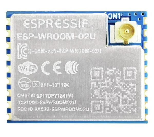
Furthermore, the ESP-WROOM-02U integrates a U.FL connector for adding an external antenna for increasing the WiFi range, which is an eye-catching feature.
It comes in two variants, ESP-WROOM-02D and ESP-WROOM-02U, where 02D is without the U.FL connector and 02U comes with it.
For using this microcontroller, we need a breakout board of some sort for programming the board and using its I/O pins for controlling stuff.
So I prepared a simple carrier board that lets us program this MCU and interact with it.
This Instructables is about the whole building process and how to use this module, so let’s get started.
Supplies
Following are the materials used in this built-
- ESP-WROOM-02U Module
- Custom PCB
- 10K Resistor 0603 Package
- 1K Resistor 0805 Package
- BLUE LED 0805 Package
- RED LED 0805 Package
- SMD tactile switch
- Male Header Pins
- Female Header Pins
- nodemcu for programming
Step 1: ESP-Wroom-02U Module
ESP-WROOM-02U is an ESP8266 chip-based microcontroller made by Espressif Systems. It comes under the category of 802.11 WiFi modules and is powered by an ESP8266EX, which is a Tensilica L106 32-bit RISC processor.
Its operating voltage is between 2.7 and 3.3 volts, and it works at a frequency of 2.4 to 2.5 GHz.
As for its average current, it consumes 80mA at least and 170mA max.
It has 11 GPIO pins that can be used as regular I/O pins.
As for its working, we can easily use this in place of regular ESP12F modules. Its specs are similar to those of ESP12F modules; the only difference is the size, which is way smaller and more compact.
Here’s its datasheet for more in-depth info- https://www.espressif.com/sites/default/files/documentation/esp-wroom-02u_esp-wroom-02d_datasheet_en.pdf
Step 2: PCB Design
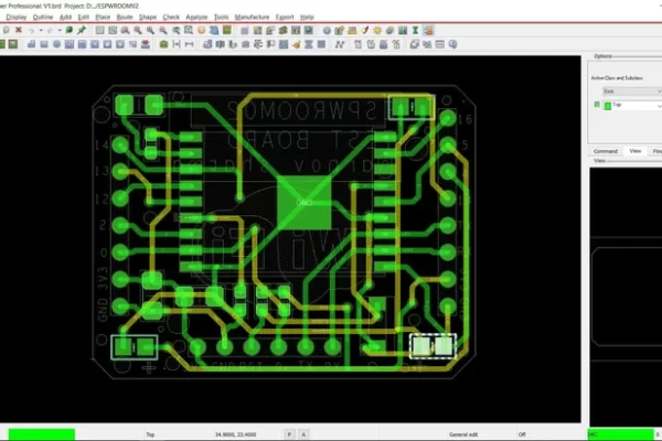
We start first by preparing a basic schematic of the ESP-WROOM Module by following its minimal configuration setup in the datasheet and replicating it into the PCB CAD software.
In the design, we connect 2x 10K resistors to the enable pin and GPIO0, both of which are pulled up to 3V3.
There’s also a 10K resistor between GPIO15 and GND, as well as one between the reset pin and 3V.
We also added a few SMD resistors: C1 and C2 are added between VCC and GND, which are 100nF and 10uF, respectively. These capacitors are for smoothing the input voltage fed into the ESP module and reducing noise.
C3 is connected between the enable pin and ground.
For accessing GPIOs, there is a two-pin header connector that connects to all GPIO ports.
As for programming, we also added a separate connector that programming is connected to with pins that are required by NODEMCU to interact with this board during programming.
Additionally, two LEDs were added to this setup for testing the Blink-Chaser sketch; both of these LEDs are connected with a common load resistor, and GPIO4 and GPIO5 were used for driving these LEDs.
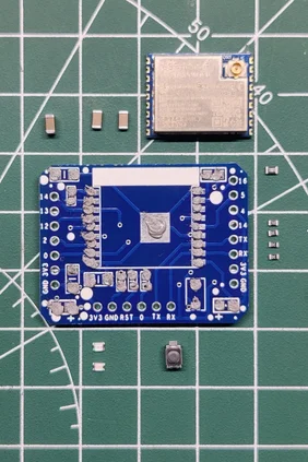
After finalizing the schematic, I prepared a small PCB that neatly holds everything around the ESP module, which is placed in the middle.
Attachments

Step 3: PCBWAY
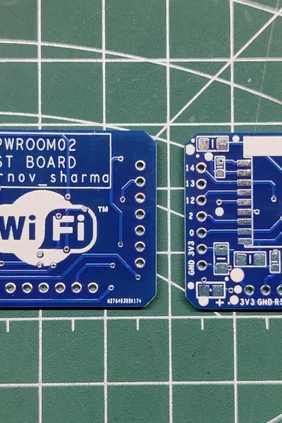
After finalizing the PCB and exporting the Gerber data, we sent it to PCBWAY for samples and placed an order for a blue solder mask with a white silkscreen.
I received PCBs within a week, and they were excellent, as expected.
I love the quality of PCBs made by PCBWAY. There are other manufacturers available, but their service is always on another level.
check out PCBWay service for getting great PCB service at less cost.
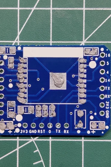
Step 4: PCB Assembly
PCB Assy is primarily comprised of four processes, which are as follows:
- Solder Paste Dispensing Process
- Pick and Place Process
- Hotplate Reflow
- THT Components
Step 5: Solder Paste Dispensing
The first step is to apply solder paste to each component pad.
We use regular Sn-Pb solder paste that has a melting temperature of 140° to 270°C, and to apply the solder paste, a solder paste syringe with a wide nozzle is used.
Step 6: Pick and Place Process
We then used an ESD tweaker to carefully pick and place all the SMD components in their assigned places one by one, which took like 30 seconds tops, but the result was a perfect PCB with all the components placed in their locations.
Step 7: Hotplate Process
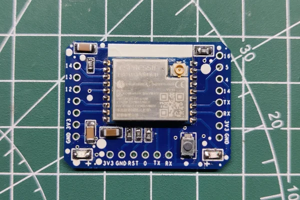
After the “pick and place process,” we carefully lifted the whole circuit board and placed it on my new Mini Hotplate.
The hotplate heats the PCB from below up to the solder paste melting temperature. As a result, the solder paste melts and components get solder on their pads.
Step 8: THT Process
Next, we add header pins to this board: male header pins for adding this setup on a breadboard and female header pins for connecting an external programmer for programming the ESP board.
Step 9: Breadboard Setup
Here’s one problem: Because I was aiming to make a rectangular board, I forgot to keep it short enough to place it normally on a breadboard.
That’s not an issue, as we can use two breadboards for placing the board, one for each side.
Step 10: Programming the Module by NodeMCU
For programming this board, we could use two methods.
1. Use an FTDI UART Board with Boot Mode Buttons
2. Use a NODEMCU Board without adding any Boot Mode Button
The method that involves programming the board with NODEMCU is by far the best way to program any ESP device or chip.
Nodemcuhas an onboard CP2102 chip, which is a UART chip for programming the MCU through TX and RX pins.
Nodemcualso has two transistors that put the ESP into boot mode, which terminates the manual process of adding external buttons and pressing them during the uploading process.
Previously, I made a programmer board that broke out these pins from the NODEMCU board.
- 3v
- GND
- RST
- GPIO0
- TX
- RX
Before the main wiring, we add a jumper between the ENABLE pin of the nodemcu and GND. This will put the ESP8266 board of NODEMCU to sleep, and we can connect an external ESP8266 board with the onboard CP2102 chip.
We connect the ESP-WROOM’s 3V, GND, RST, GPIO0, TX, and RX pins with the same pins of the nodemcu.
- First, we connect the nodemcu Board’s header pins to the ESP-WROOM female header pin connector in the right order.
- Next, we open Arduino IDE and plug the USB into nodemcu.
- we then go to the Tools menu and select the board that is being used which is in this case NODEMCU1.0 board.
- we select the right com port and hit upload.
Source: ESPWroom02 Breakout Board
- What is the main advantage of the ESP-WROOM-02U over its predecessor?
The ESP-WROOM-02U offers the same features as the ESP Series but is significantly smaller, making it suitable for badges or wearable projects. - How can the WiFi range be increased on this module?
The module integrates a U.FL connector that allows for the addition of an external antenna. - What is the difference between the ESP-WROOM-02D and ESP-WROOM-02U variants?
The 02D variant does not have a U.FL connector, while the 02U comes with one. - Why are capacitors C1 and C2 added to the PCB design?
They are placed between VCC and GND to smooth the input voltage fed into the ESP module and reduce noise. - Which pins are required for programming the board using a NODEMCU?
The required pins are 3v, GND, RST, GPIO0, TX, and RX. - Can the NODEMCU board be used without adding external boot mode buttons?
Yes, the NODEMCU has onboard transistors that put the ESP into boot mode, terminating the need for manual buttons. - What happens if you add a jumper between the ENABLE pin of the NODEMCU and GND?
This action puts the ESP8266 board inside the NODEMCU to sleep so an external ESP8266 board can use the onboard CP2102 chip. - What Arduino IDE board setting should be selected when uploading code?
You should select the NODEMCU1.0 board from the Tools menu.