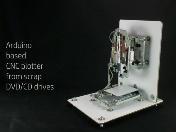
Summary of Arduino Based CNC Plotter Made From Scrap DVD/CD Drives
Summary: This project builds an Arduino-based CNC plotter using salvaged DVD/CD drive stepper motors. Images or text are converted to G-code, streamed from a PC to Arduino (running Grbl), which drives three EasyDriver stepper drivers to move X, Y, and Z axes and recreate the image on paper. The guide covers salvaging motors, identifying motor wiring, power supply and driver setup, microstepping, and flashing Grbl to the Arduino using Xloader.
Parts used in the Arduino Based CNC Plotter Made From Scrap DVD/CD Drives:
- Arduino Uno
- EasyDriver (A3967 IC based stepper motor driver) x 3
- Breadboard / copper clad board / Perfboard
- D.C. Power source (6V–30V, recommended 12V 1A)
- DVD / CD drives (scrap) x 3 (for stepper motors and lead screws)
- Acrylic glass / wood / aluminum / foam board (for mounting X/Y/Z axes)
- Aluminum L brackets
- Nuts, bolts / fasteners & washers
- Spanners
- Ball / gel pen (for drawing)
- Wires
- Female DC barrel jack
- Vernier caliper
- Multimeter
- Spring (from a pen)
- Strong epoxy adhesive
- Hot glue gun
- CPU fan (optional)
- Spacers
Indeed, the world of web has quad trillion tons of information but when you want to build anything you need all the intricate little details. There are already a number of good DIYs, Tutorials and YouTube videos on the topic but I was unable to dive into the details needed to build this project. Hence after its completion I am posting everything that is required. I will try to keep this walk through very simple and basic so that even a reader from non technical background would be able to replicate this project.
What is it all About ?
The idea behind it is very simple, first we select an image or text (that we want our machine to draw on a piece of paper). Then it is converted into a machine code with the help of a software. It is then streamed from a computer to Arduino which in turn talks to the stepper motors and tells them how much to rotate their respective shafts so as to get the code again transformed into an image or text as the original file.
Why build this project ?
Whether you are a hobbyist or an enthusiast, you want to explore capabilities of this machine or just want to build it for fun, this project will teach you a lot of things. Also if you are planning to build Arduino based bigger, better and more precise CNC, then this project is worth considering as it covers some basic aspects like how CNCs work, how to convert images/ text to Gcode, stream Gcode, configure stepper motor driver, power management and more. However, for a serious CNC enthusiast there are many more things to be explored & that aren’t covered here intentionally to keep this instructable very basic and simple for everyone to understand. I will be posting few links where ever possible to encourage readers to dive even deeper into the subject. Although it’s not extremely necessary if you just want to grasp the basics.
Disclaimer:
I am not a CNC professional, this instructable is a result of knowledge gained from books, Internet and experimentations. All the experiments and activities presented here should be tried with caution, safety and at own risk. I shall not be responsible for any damages as a result of any activities contained within this instructable.
Step 1: Requirements:
Things needed to build the project.
1. Arduino Uno
2. EasyDriver (A3967 IC based stepper motor driver) x 3
3. Breadboard / copper clad board / Perfboard
4. D.C. Power source
5. DVD /CD drives (scrap) x 3
6. Acrylic glass/ wood/ aluminum/ foam board for mounting X/Y/Z axes
7. Aluminum L brackets
8. Nuts, bolts/fasteners & washers
9. Spanners
10. Ball/Gel Pen
11. Wires
12. Female DC Barrel jack
13. Vernier caliper
14. Multimeter
15. Spring (from a pen)
16. A strong epoxy adhesive
17. Hot glue gun
18. CPU fan (optional)
19. Spacers
Step 2: Salvaging Stepper Motors
CNCs are known for their precise motions in X,Y and Z axes. The hardware responsible for executing these motions are the stepper motors. We will be using scrap DVD/CD drives for this project and in the process we shall recycle e-waste and do something that is eco-friendly.
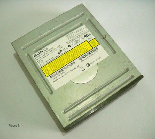
E-waste sellers / traders and computer service centers are the places where one can easily find such kind of scrapped DVD/CD drives and they almost cost nothing. I intentionally bought 3 DVD drives made by 3 different manufacturers in-order to study the variations in-terms of the steppers motors and lead screws.
Procedure for opening the drives is shown in the images, but it should be considered as a general guide as all the DVD/CD drives are not the same. Images shown are of DVD/CD re-writable drive from Sony with model no. DRU-190A. Open the drive, take out the part shown in Figure 2.9. This is the only part we will be needing for the project.
Step 3: Stepper Motor Basics and Power Supply
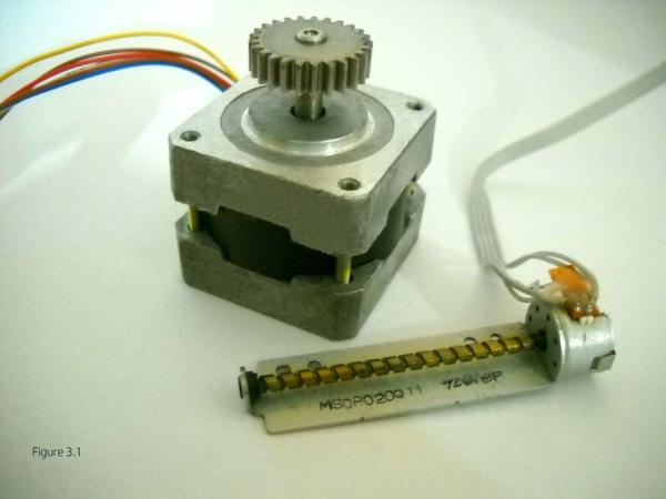
Stepper motor:
As the name implies its shaft moves in discrete steps as compared to a D.C. motor that rotate continuously when current is allowed to flow across its terminals. For continuous rotation of a stepper shaft, series of electrical pulses are required to be sent. Each pulse moves the shaft to a specific angle. Most stepper motors have a step angle of 1.8 degrees i.e., when a single electric pulse flows through its coil, the shaft moves 1.8 degrees. Thus it will take 360/1.8 = 200 steps for such motor to complete one revolution. In other words a sequence of 200 pulses needed to be sent for one revolution.
With the help of part number on the stepper motor, datasheet for the respective motor can be found online.
Most of the stepper motors from DVD/CD drive have a stepping angle of 18 degrees meaning that for one complete revolution we need to send 20 electrical pulses to the motor.
The stepper motors can be driven in different modes like Wave mode, Full step mode, Half step mode and Microstepping mode. I made a few gifs of the stepper motor to show some of these modes. As the current flows through the coils of the stepper motor they become electromagnetic and the rotor turns to a certain degree because of attraction and repulsion between the unlike and like poles of stator and rotor respectively.
Click here for more information on stepper motors, type, Unipolar / Bipolar and more.
Identifying stepper motor wires:
These are generally Bipolar stepper motors. Mostly a piece of strip leads through their terminals that already have wires arranged in sequence.
If you accidentally rip off the strip completely ( like I did with my first motor) then you will have to figure it out yourself. This is necessary because if you don’t hook up things correctly you might notice motor’s shaft moving back and forth.
(If motor’s shaft rotates correctly in one direction then you might skip this section)
There are two coils in the motor and we have to identify the wires that are part of the same winding. It can be done with any of the method described below.
Method 1: Turn multimeter’s knob in resistance mode and select 200 ohms.With one probe touch anyone terminal of the motor and keep shifting the second probe on the remaining terminals until your multimeter shows some reading, no reading means not a pair. I got a reading of 6.3 ohms, your’s may vary but that’s fine. So in this way you will find first pair of wire, the remaining two should be your second pair, confirm it.
Method 2: Same can be done by turning the knob in continuity/ diode mode, in this case you will hear a beep and get some reading on its screen as well.
Method 3: You will need a 9v battery, a resistor and a LED . Connect them with wires as shown in Figure 3.4.
There are many online LED resistor calculators if you have a battery or a power source of different voltage. While connecting the LED please note the polarity if connected incorrectly it will never glow.
Make the circuit and touch the test lead to anyone terminal of the motor and keep shifting the second lead on the remaining terminals until the LED glows. If it glows you have found a pair.
After finding out the pairs connect the wires from motor to the motor driver as shown in Figure 3.5.
At this point it looks quite tempting and hard to resist from connecting everything and powering up the circuit. But there are few things we should know about the power supply and motor driver which in-turn will not only save our time but the module itself.
Power supply:
Use power supply from 6v to 30v anything below it won’t probably give better performance and above maximum range could fry the electronics. Remember higher the voltage and current hotter the A3967 chip will get during operation. I mentioned A3967 chip as I will be discussing EasyDriver module based on the same chip.
Stepper motors that we are using in the project requires 100 mA to 200 mA current per coil. Since we will be using 3 steppers, we need a power supply capable of delivering current above 1 Amp. I used 12v 1 Amp for this project which was adequate everything stays cool . At 12v 2 Amps I noticed both EasyDrivers and stepper motors getting very hot. If excess current is delivered EasyDriver gets extremely hot and after reaching a specific temperature it enters thermal shutdown mode in order to protect the chip. If this happens disconnect the power source and let things cool down for a while.
Step 4: Know Your Motor Driver
We need a stepper motor driver to be able to drive these motors efficiently. There are number of ICs and circuit diagram online which should serve the purpose and could be cheaper to implement. However for beginners I would recommend a prefabricated stepper driver module. These are not only convenient but are lot safer as you won’t end up blowing something by the back EMF of the motors.
Other popular drivers include Big Easy Driver A4988, DRV8825 modules.
EasyDriver module:
It is based on Allegro’s A3967 chip. It can work with anything that can output 0 to 5v or 0 to 3.3v pulse.The module can provide a minimum of 150 mA (milli ampere) and a maximum of 750 mA per coil. This can be adjusted by turning the trim pot as per the current requirements of the stepper motor. The silver screen shows MIN/MAX markings just below the trim pot. This marking indicates the direction you need to rotate the pot so as to decrease or increase the amount of current going to the motor. But you can’t blindly trust the silver screen as it may be sometimes printed falsely.
If after powering up the module, motor gets extremely hot then turn the pot very gently towards the MIN direction and if the MIN/MAX markings are correct then the motor should cool down otherwise move it in the opposite direction. The motor gets hot if it is being delivered excess amount of current. Current is to be lowered to a limit such that motor stays cool when it is idle but at the same time not low enough to lose a step. Knowing actual current being delivered is not that crucial for this project, with trial and error one can easily set the right amount of current.
Those who are interested in finding out the actual amount of current being delivered, link to the formula is given below others may skip this part and may can continue with the above method.
For current calculation per coil you may refer to this article the author had simplified it very nicely please click here for more information. This link is published on schmalzhaus.com
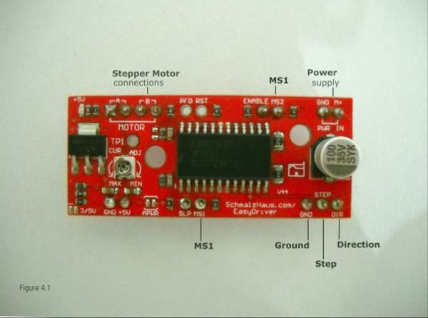
Pin description :
1) GND (Ground/negative) : There should be 3 pins on the EasyDriver board labelled as GND, all of them are connected together inside the board. Connect the negative of power supply and Arduino to one or more GND pins of EasyDriver.
2) M+ : This is the power supply pin. It should be between 6v to 30v.
3) A and B : These are the motor connection pins. Connect one pair to A and other to B.
4) STEP : This is to be connected to Arduino which will be sending digital signals that is 0 or 5v (or it could be 0 or 3.3v if you’ve set your EasyDriver that way)
5) DIR : This needs to be 0 or 5v.
Motor drivers generally don’t like reverse polarity at their power input pins and also sudden disconnection of motors when they are energized. I haven’t tried that yet, but to be on safer side let’s not do that.
For more information on EasyDriver stepper motor module click here
Microstepping :
Microstepping simply means breaking a single step into number of steps. By default EasyDriver is set to 1/8th microstepping mode. However it can operate in four different modes viz., Full, half, 1/4th, 1/8th steps. MS1 and MS2 pins decide the microstepping modes.
Here HIGH = 5v and LOW = 0v. Pull these pins accordingly to enable the desired microstepping mode.
1) MS1 (LOW) and MS2 (LOW) = Full step
2) MS1 (HIGH) and MS2 (LOW) = Half step
3) MS1 (LOW) and MS2 (HIGH) = 1/4th step
4) MS1 (HIGH) and MS2 (HIGH) = 1/8th step
See Figure 4.1 for MS1 and MS2 pins.
With adequate knowledge, we can now step ahead and connect the stepper motors.
Step 5: Flashing Grbl to Arduino:
Grbl is a free, open source, high performance software for controlling the motion of machines that move, that make things, or that make things move, and will run on a straight Arduino
The Grbl software that I will be talking about in this section is a special kind of hex file and can’t be uploaded through Arduino IDE directly. We need to use a software called Xloader for this purpose. This is the method which I used and its quite simple and hassle free.
But if you wish to use the Arduino IDE only instead of Xloader then you have to download the Grbl source code first. Its very well documented on GitHub. For step by step instructions click here.
For more information on Grbl click here
Download link:
- For Grbl file click here
On the Grbl download page you will find different versions of hex files. I downloaded the file with name “grbl_v0_8c_atmega328p_16mhz_9600.hex” for this project. After downloading the required softwares connect Arduino to computer through USB cable. Your computer should make a sound telling that something is connected. Identify the COM port your Arduino is connected.
For com port identification there are few ways:
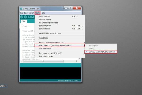
First method: Open Arduino IDE, click on Tools tab. Move cursor over Port: and select the port which shows (Arduino/Genuino Uno) see Figure 5.1.
Second method (on Windows 7): Right click on ‘Computer’ icon, select ‘Manage’ and click it. Then click ‘Device Manager’, click Ports (COM & LPT) it should show the port to which Arduino Uno is connected (see Figure 5.2). In my case it is COM13 your’s could be different .
Once you know on which COM port your Arduino is connected open the Xloader software, select the respective ‘COM port’, make initial settings as shown in Figure 5.3 and finally click ‘Upload’ button.
While the Grbl file is being uploaded to the Arduino the Tx & Rx LEDs appears to be continuously in ‘on state’ for few a seconds. During this period DO NOT DISCONNECT ARDUINO FROM THE COMPUTER.
After the completion of process a message at the bottom just below the ‘Upload’ , ‘About’ button appears saying ‘26486 bytes uploaded’ (see Figure 5.4). This a confirmation that Grbl file has been successfully sent to Arduino and now it can be disconnected safely from the computer if you want.
Source: Arduino Based CNC Plotter Made From Scrap DVD/CD Drives
- What is the basic idea behind this project?
Select an image or text, convert it to machine code (G-code), stream it from a computer to an Arduino running Grbl, which controls stepper motors to reproduce the image or text on paper. - Why use scrap DVD/CD drives?
They provide affordable stepper motors and lead screws, recycling e-waste while supplying parts needed for X/Y/Z axes motion. - How do stepper motors move and what are typical step angles?
Stepper shafts move in discrete steps; many motors have 1.8 degree steps (200 steps/rev) while DVD drive steppers often have 18 degree steps (20 steps/rev). - How can you identify stepper motor wire pairs?
Use a multimeter in resistance or continuity mode, or test with a 9V battery, resistor, and LED to find coil pairs. - What power supply is recommended?
Use 6V to 30V; the author used 12V 1A which was adequate—higher voltage/current can overheat EasyDriver and motors. - What does the EasyDriver do and what are its limits?
EasyDriver (A3967) drives stepper motors, supports about 150 mA to 750 mA per coil (adjustable via trim pot), and accepts 6V–30V supply. - How is microstepping configured on EasyDriver?
MS1 and MS2 pins set stepping: LOW/LOW full step, HIGH/LOW half step, LOW/HIGH 1/4 step, HIGH/HIGH 1/8 step. - How do you flash Grbl to Arduino?
Download the appropriate Grbl hex file and use Xloader to select the Arduino COM port and upload the hex; do not disconnect during upload. - Can Arduino IDE be used to install Grbl instead of Xloader?
Yes; you must download Grbl source code from GitHub and follow documented steps to upload via Arduino IDE. - What precautions are advised when powering motors and drivers?
Avoid reverse polarity and sudden disconnection; reduce trim pot current if motors or drivers run hot to prevent thermal shutdown.