Description
This module can be used to measure temperature using RTD (resistive temperature detectors) temperature sensors.
It produces an analog voltage that is proportional the temperature of the probe.
The module contains a multiplexer to enable measurement of up to 4 temperature probes.
Design
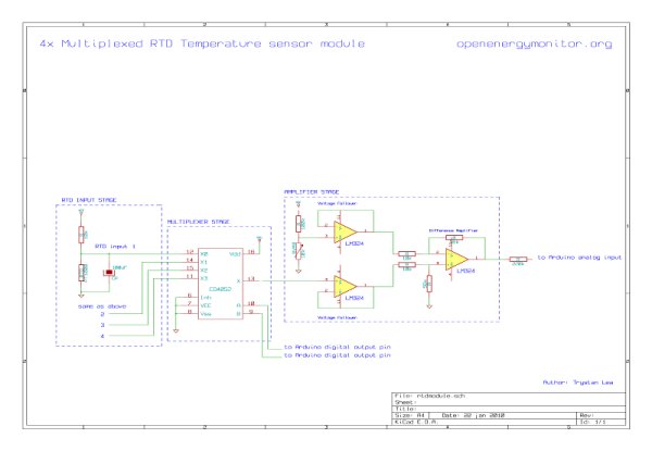
RTD Temperature sensors change their resistance with temperature. The resistance change is converted to a voltage change with a simple voltage divider. The output of which passes through a low pass filter to remove any unwanted high frequency noise components.
In order to use only one amplifier circuit and one arduino analog input the temperature sensing input stages are selected sequentially using a multiplexer.
The difference amplifier then takes the output voltage of the selected input stage and converts it to a voltage that uses the full range of the arduino analog input maximizing accuracy.
Component list
RTD Input stage
3x PT1000 RTD Temperature sensors.
3x 10k resistors
3x 100uF capacitors
Multiplexer stage
1x CD4052 Multiplexer
Amplifier stage
1x LM324 opamp
1x 100k resistor
1x 10k potentiometer
2x 10k resistor
2x 56k resistors
1x 220k resistor
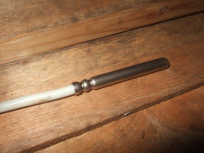
RTD Temperature sensor
The RTD sensors I’m using are PT1000 sensors: their resistance is 1000ohms at 0C, another popular value is the PT100 which is 100ohms at 0C, the setup here can be easily modified for PT100’s just change the 10k resistor on the input stage voltage divider for a 1k resistor.
RTD temperature sensors have a fairly linear increase in resistance to temperature increase (although not completely). The temperature at a given resistance is given by a look-up table:
PT1000 resistance table
| C | Ohms | C | Ohms | |
| -10 | 961 | 55 | 1213 | |
| -5 | 980 | 60 | 1232 | |
| 0 | 1000 | 65 | 1252 | |
| 5 | 1019 | 70 | 1271 | |
| 10 | 1039 | 75 | 1290 | |
| 15 | 1058 | 80 | 1309 | |
| 20 | 1078 | 85 | 1328 | |
| 25 | 1097 | 9 | 1347 | |
| 30 | 1117 | 95 | 1366 | |
| 35 | 1136 | 100 | 1385 | |
| 40 | 1155 | 105 | 1404 | |
| 45 | 1175 | 110 | 1423 | |
| 50 | 1194 | 115 | 1442 |
The changing resistance of the RTD can be converted into a changing voltage by placing the RTD in a simple voltage divider circuit with a constant voltage source and then measuring the voltage across the RTD. As in the following schematic:
The resistance of the RTD can be found from the output voltage of the voltage divider by the following equation:
RTD Resistance = Vout *R / (Vcc – Vout) rearranged for Vout = Vcc*RTD / (RTD + R)
The considerations when choosing R are:
- Increasing R minimizes self heating of the RTD: minimizing error.
- Increasing R decreases the magnitude of the voltage change per degree: decreasing signal to noise ratio.
- Increasing R increases noise caused by the resistors: decreasing the signal to noise ratio.
So to choose R we need to balance these considerations. I decided to go with a 10k resistor.
With a supply voltage of 5V and R =10k, the voltage out at -10C will be 0.438V and at 115C will be 0.630V. This voltage can be measured straight by the Arduino analog inputs, however with default settings the accuracy will not be great. The arduino ADC with the default ADC reference voltage of 5V divides 0 to 5V in to 1023 divisions, 0.438V to 0.630V therefore has 39 divisions and 125C range divided by 39 is equal to an accuracy of about 3.2C. However by using the full Arduino ADC range we can do much better, the best accuracy achievable would be 125C / 1023 = 0.122C.

Obtaining 0V at minimum temperature
The voltage at -10C is 0.438V so a circuit is needed to subtract 0.438V from the voltage output of the RTD input stage. This can be done with a difference amplifier.
For more detail: 4x Multiplexed RTD Temperature sensor module

