Summary of 3x3x3 LED cube shield using arduino
This article guides beginners through building a 3x3x3 LED cube using a kit. It details identifying LED polarity (Anode/Cathode), testing LEDs with a battery, and assembling three 9-LED layers on a PCB. The process involves soldering connections within layers and stacking them correctly to ensure positive terminals connect to positives across levels. Essential tools like a soldering iron and safety gear are emphasized for success.
Parts used in the 3x3x3 LED Cube:
- PCB
- 27 LED's
- 2 - 6 Pins for Arduino
- 2 - 8 Pins for Arduino
- 3 Resistors
- Foam Guide
- Small Wire
- Medium Wire
- Large Wire
What should be in your kit:
1 – PCB
27 – LED’s
2 – 6 Pins for Arduino
2 – 8 Pins for Arduino
3 – Resistors
1 – Foam Guide
1 – Small Wire
1 – Medium Wire
1 – Large Wire
You will need: Solder Iron, Solder, Wire Cutters, Wire Strippers, Safety Googles, Helping hands are always good (but not manditory) and a really GREAT ATTITUDE!!!
to by a kit go to http://lwjmstore.blogspot.com/
In the below pictures I will be switching between RED LED’s and GREEN LED’s. My mom made a GREEN one…some parts didn’t turn out so good. She did try – and she is a VERY beginner! Good Job Mom!
Have FUN!

Step 1: Information
LED’s: All LED’s have a Positive (+) and a Negative (-) As you can see on the picture below. The Positive (+) is longer than the Negative (-) You will always be bending the Negative (-). The official term for the Negative is “Cathode” and for the Positive is “Anode” For these directions we will use short and long.
Testing your LED’s: I’ve tested every single LED. However if you’d like to test to make sure…here’s how to do it. Take a Lithium battery, stick the LED with the long led on the side of the battery marked with a “+”. Press the Leds against the battery. The light should turn on. If not…you’ve got yourself a bad LED.
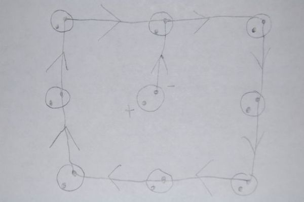
Guide Sheet: I used this as my template. If you ever get confused (easy to do) refer back to the guide sheet. This will tell you how to bend and placement of the LED’s.
Each circle has 2 dots. The one with the arrow is the Negative (-) and the one standing alone is the Positive (+). This shows you which way to bend your Negative (-) led
Step 2: Connecting your LED’s
ALWAYS FOLD DOWN THE NEGATIVE (-)..SHORTER SIDE
1) Start with the center hole. Folding down Negative (-) on the right side.
2) Place the second LED in as shown. Solder them together. Don’t worry about the end of the LED being too long. We will be trimming them.
3) Place the third LED in as shown. Solder them together.
Continue on until all 9 LED’s are soldered together.
Before cutting the extra wire. Take another look to make sure all your LED’s are going the correct way and you folded down the Negative (-) This is the time to catch a mistake…you can always unsolder and fix it.
Using your wire cutters, cut off the extra wire. Mostly should be on the 4 corners.
You should have.. (3) 9 pin LED’s squares
Step 3: Solder all 3 levels together
Now the tricky part starts. Stacking them together.
Put one LED piece back into the foam. You can find something to slide in between as shown.
Put your 2nd layer on. You will be soldering the Positive (+) to the Positive (+) on the next layer as shown. You may need to bend the wires so they meet. *Please note that the picture above is showing how to stack the layers. It has not been soldered together. If you connect one Positive (+) to a Negative (-) your LED will not light up in the end.
Do the same with the 3rd layer. *Please note that the picture above is showing how to stack the layers. It has not been soldered together.
This is what you should have in the end. This is the one my mom did…alittle crooked, but that’s ok. As long as all the soldering is good the LED’s will still shine.
Set your LED “Cube” off to the side. Let’s work on the PCB.
For more detail: 3x3x3 LED cube shield
- How do I identify the positive and negative sides of an LED?
The positive side is the longer leg called the Anode, while the negative side is the shorter leg called the Cathode. - Can I test my LEDs before soldering?
Yes, you can test them by pressing the long leg against the positive side of a lithium battery; if it lights up, the LED is good. - Which side of the LED should always be folded down during assembly?
You should always fold down the negative or shorter side of the LED. - What happens if I connect a Positive terminal to a Negative terminal between layers?
If you connect one Positive to a Negative, your LED will not light up in the end. - How many LED squares should I create in Step 2?
You should have three 9 pin LED squares after cutting the extra wire. - What tool is recommended to help hold parts while soldering?
Helping hands are suggested as they are always good to have, though not mandatory. - Where can I find more detailed instructions for this project?
More detail is available under the title 3x3x3 LED cube shield.