Summary of 12$ 30MHz signal generator using Arduino
This article details a DIY project to build a compact, affordable 30 MHz signal generator for $12 using an Arduino Pro Mini and an AD9850 DDS synthesizer module. The device generates sine, square, sawtooth, and triangular waves, featuring an LCD display for frequency readout and a rotary encoder for adjustments. It operates on a 5V power supply with a maximum current of 270mA, offering a portable solution for testing and troubleshooting electronic circuits.
Parts used in the 30 MHz Signal Generator:
- Arduino Pro mini
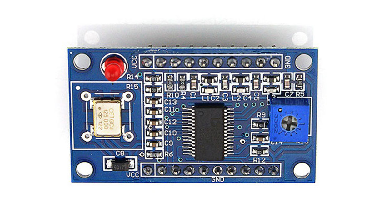
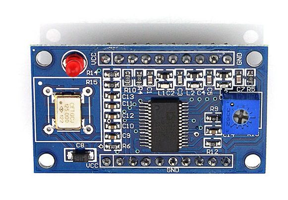
- AD9850 (DDS Synthesizer)
- 16×2 LCD Display (Hitachi HD 44780)
- Rotary Encoder
- CP2102 (USB to serial converter)
A signal generator is an electronic device that generates electronic signals and waveforms. These electronic signals are either repeating or non-repeating as per the requirements and field of applications. It is generally used in designing, testing, troubleshooting and repairing electronic devices.
This instructable shows a full guide on how to make a 30 MHz signal generator for 12$, using an Arduino and an AD9850 DDS synthesizer module. The circuit is pretty simple and small enough to fit in your pocket. Kedar Nimbalkar, the author of the instructable, says:
A precession signal generator is very easy and affordable to make using an Arduino and DDS synthesizer (ad9850) . It’s World’s first smallest portable signal generator.
You can make decent 0 -30 MHZ frequency Signal generator only in 12$ .
Parts List:
1. Arduino Pro mini
2.AD9850 (DDS Synthesizer)
3.16×2 LCD Display ( Hitachi HD 44780 )
4.Rotary Encoder
5. CP2102 (or any USB to serial converter)
I think you are familiar with all of the above items except the AD9850 (DDS Synthesizer). First of all, you need to know what does DDS stand for.
Direct digital synthesizer (DDS) is a type of frequency synthesizer used for creating arbitrary waveforms from a single, fixed-frequency reference clock. A basic Direct Digital Synthesizer consists of a frequency reference, a numerically controlled oscillator (NCO) and a digital-to-analog converter (DAC).
AD9850 (DDS Synthesizer):
Circuit Diagram Of Signal Generator:
The circuit diagram is very simple. You can make it on a breadboard, or just solder components end to end to make it more compact.
The Arduino sends digital signals to AD9850 and the module generates analog output Sine wave. The display, which is connected to Arduino, shows output frequency and step increment/decrement value. The rotary encoder is for changing frequency. Though the AD9850 module can generate up to 40 MHz frequency, but after 30 MHz the output frequency becomes unstable. So in this circuit, the maximum frequency is limited to 30 MHz.
You can make a decent 0-30 MHz frequency signal generator for only 12$ . If you are pro “overclocker”, then 40 MHz in same price .
The signal generator runs on 5 Volt power supply and current should not exceed 270mA.
Arduino Sketch:
The Arduino code is HERE.
Output:
Watch the video which demonstrates the 12$ signal generator.
https://youtu.be/1SgcjxacGlQ
- How much does it cost to make this signal generator?
You can make a decent 0-30 MHz frequency signal generator for only $12. - What is the maximum frequency limit for stable output?
The maximum frequency is limited to 30 MHz because the output becomes unstable after that point. - Can this circuit generate up to 40 MHz?
Yes, if you are a pro overclocker, you can achieve 40 MHz at the same price, though stability may vary. - What type of waveforms can the AD9850 generate?
The AD9850 generates spectrally pure analog output sine waves using direct digital synthesis technology. - How do you change the frequency on this device?
The rotary encoder is used for changing the frequency of the generated signal. - What power supply does the signal generator require?
The signal generator runs on a 5 Volt power supply where current should not exceed 270mA. - Does the display show the step increment or decrement value?
Yes, the display connected to the Arduino shows the output frequency and the step increment or decrement value. - Is the circuit design complex to assemble?
No, the circuit diagram is very simple and can be made on a breadboard or by soldering components end to end.