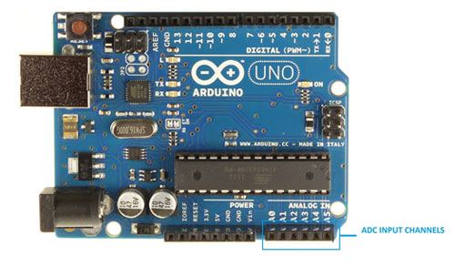
In this tutorial we are introducing concept of ADC (Analog to Digital Conversion) in ARDUINO UNO. Arduino board has six ADC channels, as show in figure below. Among those any one or all of them can be used as inputs for analog voltage. The Arduino Uno ADC is of 10 bit resolution (so the integer values from (0-(2^10) 1023)). This means that it will map input voltages between 0 and 5 volts into integer values between 0 and 1023. So for every (5/1024= 4.9mV) per unit.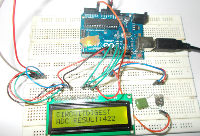
In all of this we are going to connect a potentiometer or pot to the ‘A0’ channel, and we are going to show the ADC result on a simple display. The simple displays are 16×1 and 16×2 display units. The 16×1 display unit will have 16 characters and are in one line. The 16×2 will have 32 characters in total 16in 1st line and another 16 in 2nd line. Here one must understand that in each character there are 5×10=50 pixels so to display one character all 50 pixels must work together, but we need not have to worry about that because there a another controller (HD44780) in the display unit which does the job of controlling the pixels (you can see it in LCD unit, it is the black eye at the back).
Components Required
Hardware: ARDUINO UNO, power supply (5v), JHD_162ALCD (16x2LCD), 100uF capacitor, 100KΩ pot or potentiometer, 100nF capacitor.
Software: arduino IDE (Arduino nightly)
Circuit Diagram and Explanation
In 16×2 LCD there are 16 pins over all if there is a back light, if there is no back light there will be 14 pins. One can power or leave the back light pins. Now in the 14 pins there are 8 data pins (7-14 or D0-D7), 2 power supply pins (1&2 or VSS&VDD or GND&+5v), 3rd pin for contrast control (VEE-controls how thick the characters should be shown), and 3 control pins (RS&RW&E).
In the circuit, you can observe I have only took two control pins, the contrast bit and READ/WRITE are not often used so they can be shorted to ground. This puts LCD in highest contrast and read mode. We just need to control ENABLE and RS pins to send characters and data accordingly.
The connections which are done for LCD are given below:
PIN1 or VSS to ground
PIN2 or VDD or VCC to +5v power
PIN3 or VEE to ground (gives maximum contrast best for a beginner)
PIN4 or RS (Register Selection) to PIN8 of ARDUINO UNO
PIN5 or RW (Read/Write) to ground (puts LCD in read mode eases the communication for user)
PIN6 or E (Enable) to PIN9 of ARDUINO UNO
PIN11 or D4 to PIN10 of ARDUINO UNO
PIN12 or D5 to PIN11 of ARDUINO UNO
PIN13 or D6 to PIN12 of ARDUINO UNO
PIN14 or D7 to PIN13 of ARDUINO UNO
The ARDUINO IDE allows the user to use LCD in 4 bit mode. This type of communication enables the user to decrease the pin usage on ARDUINO, unlike other the ARDUINO need not be programmed separately for using it in 4 it mode because by default the ARDUINO is set up to communicate in 4 bit mode. In the circuit you can see we used 4bit communication (D4-D7).
So from mere observation from above table we are connecting 6 pins of LCD to controller in which 4 pins are data pins and 2 pins for control.
Read More: How to Use ADC in Arduino Uno?