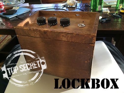
Hey everyone, I wanted to share a project I just finished up. I built a super secret locking box for my girlfriends little brother. He has a knack for creative lego building so I thought it would be a good idea to open him up to the Arduino as soon as possible. The super secret locking box will only open for those with right password or there is a hidden way to reset the passcode so that no prying little sister would ever be able to figure it out. That is, unless she finds this instructable. The secret method involves using some capacitive touch sensing.
The Arduino stays asleep to conserve battery and only wakes when the button is pressed. Upon waking, there are two paths to go down, flash the green LED, unlock, and go back to sleep OR light up the red LED and wait for 20 seconds for the right passcode, then go to sleep. In the period before it goes to sleep, if you touch(not press) the button for 5 seconds, the passcode will be set to whatever the code is currently. It will then unlock and go back to sleep. The 20 seconds timer restarts every time the button is pressed.
Parts
ATmega168/328 on a PCB or an Arduino with a breadboard
Wood Box
small servo
3x Potentiometers & knobs
push button
RGB LED
2x 100 ohm resistors
150 ohm resistors
battery pack
wire
depending on how you make the latch, these parts will be up to you, I used 1/4″ square dowels to make the latch and supports
Tools
Skills with a Dremmel
Soldering Iron
Hot Glue Gun
Wood Glue (I recommend Gorilla Wood Glue, the non-foaming kind)
If anyone can decipher the suspected Japanese characters, I would really love to know the original purpose of the box.
UPDATE:
He loved it!
Step 1: Cut and wire it up!
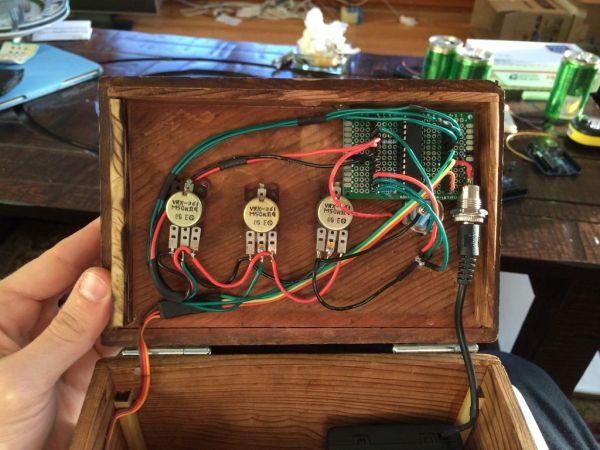
You will need to measure out where to cut 5 holes for the pots, LED, and button. Make sure to leave space for either the Arduino or a breadboard/pcb standalone. I chose to use an ATmega 328P-PU standalone running 8MHz internal clock to minimize battery consumption. On sleep mode, theoretically should only draw a few uA which is worlds better that the 25mA the UNO was consuming.
If you plan to use the arduino development board instead of a standalone version, be sure to bypass the 5V regulator by using the 5V pin to power it instead of VIN or the barrel jack. Trying to conserve any battery is pointless if it is being used.
Connect 5V, GND and data lines to the appropriate pins. Remember to use resistors on the LED, red needs 150 ohms while blue and green need 100 ohm resistors.
Remember, the pots must be connect to analog pins.
Whichever battery pack you choose must output a max voltage of 5.5V and a minimum of 4.5v. (3AA wired in series should work). The ATmega328 will run nicely anywhere from 1.8 to 5.5v but the servo requires a bit more juice. The data sheet for a 9g servo says 4.8v minimum. Since it is more common to find packs with 4 batteries which would produce 6v, a Shottkey diode can be used to drop to voltage to 5.6v. I don’t think an extra .1v will damage the ATmega.
EDIT:
3x 1.5v alkaline AA wired in series = 4.5v
I used 4x 1.2v lithium batteries for 4.8v
For more detail: Super Secret Lock Box w/ Capacitive Touch