There are several good Jeopardy/Game Show lockout buttons/buzzers, but none incorporate the timing rules of Jeopardy. I am learning about the Arduino and I thought that this would be a great project to practice with.
The rules include a question reading period with no timeout to reading the question. During this period, any player who tries to ring in receives a 250 ms penalty. When the question is finished, players have a five second window to ring in and a five second timeout to answer. After an answer timeout or a wrong answer, there is another five second window to ring in and the flow proceeds until a player answers correctly or all players have rung in and have answered incorrectly or the ring-in window has timed out.
Initially, I built my project on a solder-less breadboard. When I got the connections worked out I moved to a Radio Shack Universal Component PC Board with 780 Holes which I happened to have bought several years ago. My intention was to use as much from my junk box as possible. I recommend that, if you plan to make this, you consider using the MakerShield Kit from Maker Shed. It is more expensive but it will have the parts you need and save time.
I have not included a lot of detailed instructions on wiring the PC board, since I don’t recommend that you use the same board as I did and the circuit is fairly simple. The circuit and the breadboard layout are included.
Step 1: Gather Materials
As I said, much of what went into this came from my junk box. I did have to purchase the push-button switches. The minimum parts list is:
1 Blue LED
1 Green LED
1 Red LED
1 Yellow LED
1 White LED
6 Pushbutton (Radio Shack Catalog #: 275-1556 or Catalog #: 275-1548)
6 10k Ω Resistor
4 220 Ω Resistor
1 Arduino (processor ATmega; variant Arduino UNO R3)
1 solder-less breadboard
jumper wires
In addition, if you want to go beyond breadboarding, you might need:
5 LED Holders (Radio Shack Catalog #: 276-079)
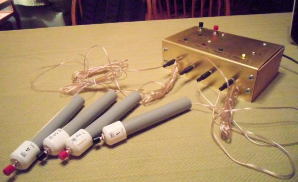
1 Project Box (I used a piece of sheet metal bent to a box size of 5″x8″x3″, with wood ends. This size provided plenty of room.)
4 3.5MM Mono Male Plug (Ebay)
4 Panel 3.5mm Female Mono Headphone Jack (Ebay)
4 5″ sections 1/2″ PVC pipe
4 1/2″ PVC end caps
20 gauge or 22 gauge ZIP Cord or Speaker Wire
1 MakerShield Kit (MakerShed)
or
1 prototyping breadboard
1 set Shield stacking headers for Arduino (Adafruit)
After I had built the project, I noticed some other projects which had used the MakerShield board with a solder-less breadboard on its top. This is a great idea because it allows you to easily put the project together and then reuse the MakerShield when you move on to the next project.
Step 2: The Ring-In Buttons
The Ring-In Buttons each consist of a 5″ length of 1/2″ PVC pipe, a 1/2″ PVC pipe cap, a push-button switch and the wire to the game console (the Project Box). Begin with drilling a hole on the end of the pipe cap for the switch. The switches I used require a 1/4″ hole. The thickness of the end of the cap will prevent the threads of the switch from protruding sufficiently to screw on the mounting nut, so the end must be sanded or ground down. I used a disc sander.
Step 3: Let the Wiring Begin
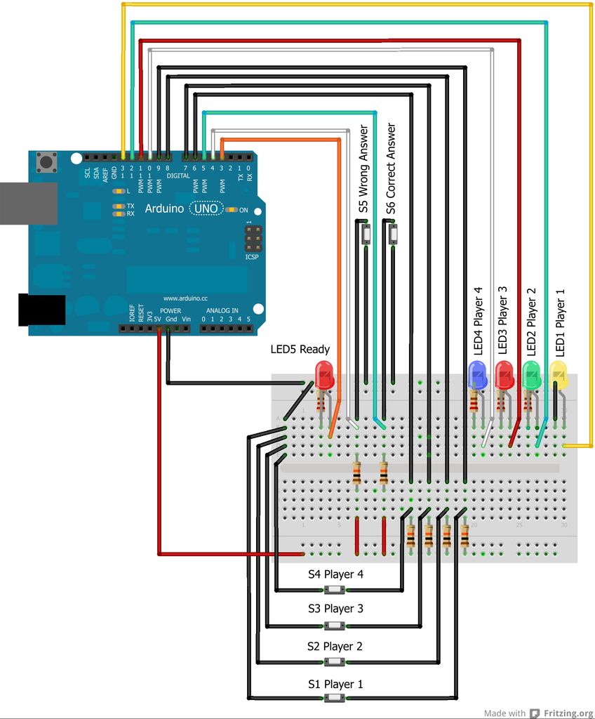
If you follow the breadboard layout, cross checking with the schematic, you should be able to upload the Arduino sketch below and, after setup, see the player LEDs light in chase-mode.
 JeopardyButtons.fzz.zip
1 Green LED
1 Red LED
1 Yellow LED
1 White LED
6 Pushbutton (Radio Shack Catalog #: 275-1556 or Catalog #: 275-1548)
6 10k Ω Resistor
4 220 Ω Resistor
1 Arduino (processor ATmega; variant Arduino UNO R3)
1 solder-less breadboard
jumper wires
In addition, if you want to go beyond breadboarding, you might need:
5 LED Holders (Radio Shack Catalog #: 276-079)
1 Project Box (I used a piece of sheet metal bent to a box size of 5″x8″x3″, with wood ends. This size provided plenty of room.)
4 3.5MM Mono Male Plug (Ebay)
4 Panel 3.5mm Female Mono Headphone Jack (Ebay)
4 5″ sections 1/2″ PVC pipe
4 1/2″ PVC end caps
20 gauge or 22 gauge ZIP Cord or Speaker Wire1 MakerShield Kit (MakerShed)
or
1 prototyping breadboard
1 set Shield stacking headers for Arduino (Adafruit)[/box]
For more detail: Jeopardy Ring-in Buttons with Built-in Rules using Arduino