Most of us would be familiar with the 16×2 Dot matrix LCD display that is used in most of the projects to display some information to the user. But these LCD displays have a lot of limitation in what they can do. In this tutorial we are going to learn about OLED displays and how to use them Arduino. There are lots of types of OLED displays available in the market and there are lots of ways to get them working. In this tutorial we will discuss about its classifications and also which will be best suited for your project.
Hardware Required:
- 7pin 128×64 OLED display Module (SSD1306)
- Arduino UNO/Nano
- Breadboard
- Connecting Wires
- Computer/Laptop
Getting to know about OLED Displays:
The term OLED stands for “Organic Light emitting diode” it uses the same technology that is used in most of our televisions but has fewer pixels compared to them. It is real fun to have these cool looking display modules to be interfaced with the Arduino since it will make our projects look cool. We have covered a full Article on OLED displays and its types here.
We are using a Monochrome 7-pin SSD1306 0.96” OLED display. The reason for choosing this display is that it can work on three different communications Protocols such as the SPI 3 Wire mode, SPI four wire mode and IIC mode. This tutorial will cover how to use the module in SPI 4-wire mode as it is the fastest mode of communication and the default one.
The pins and its functions are explained in the table below.
|
Pin Number |
Pin Name |
Other Names |
Usage |
|
1 |
Gnd |
Ground |
Ground pin of the module |
|
2 |
Vdd |
Vcc, 5V |
Power pin (3-5V tolerable) |
|
3 |
SCK |
D0,SCL,CLK |
Acts as the clock pin. Used for both I2C and SPI |
|
4 |
SDA |
D1,MOSI |
Data pin of the module. Used for both IIC and SPI |
|
5 |
RES |
RST,RESET |
Resets the module (useful during SPI) |
|
6 |
DC |
A0 |
Data Command pin. Used for SPI protocol |
|
7 |
CS |
Chip Select |
Useful when more than one module is used under SPI protocol |
In this tutorial we will simply operate the module in 4-Wire SPI mode, we will leave the rest for some other tutorial.
Arduino community has already given us a lot of Libraries which can be directly used to make this a lot simpler. I tried out a few libraries and found that the Adafruit_SSD1306 Library was very easy to use and had a handful of graphical options hence we will use the same in this tutorial. But, if your project has a memory/speed constraint try using the U8g Library as it works faster and occupies less program memory.
Hardware and connections:
The Circuit Diagram for SSD1306 OLED interfacing with Arduino is really simple and is shown below
We simply have establish a SPI communication between the OLED module and Arduino. Since the OLED runs on 3V-5V and consumes very little power it does not need an external power supply. You can simply use wires to make the connection or use a breadboard as I have used so that it is easy to experiment. The connection is also listed in tale below
|
S.No |
Pin Name on OLED module |
Pin Name on Arduino |
|
1 |
Gnd, Ground |
Ground |
|
2 |
Vdd, Vcc, 5V |
5V |
|
3 |
SCK, D0,SCL,CLK |
10 |
|
4 |
SDA, D1,MOSI |
9 |
|
5 |
RES, RST,RESET |
13 |
|
6 |
DC, A0 |
11 |
|
7 |
CS, Chip Select |
12 |
Note: You will not be able to visualize any backlight/glow on the OLED module just by powering it. You have to program it correctly to notice any changes on the OLED display.
Programming the SSD1306 OLED display for Arduino:
Once the connections are ready you can start programming the Arduino. As said earlier we will be using the Adafruit library and GFX library for working with this OLED module. Follow the steps to test run your OLED display.
Step 1: Download the Adafruit Library and the GFX library from Github using the link below
Step 2: You should have download two Zip files. Now add them to your Arduino by following
Sketch->Include Library -> Add Zip library as shown below. Then select the library we just downloaded. You can select only one library at a time, hence you have to repeat this step again.
Step 3: Launch the example Program by selecting File->Examples->Adafruit SSD1306 -> SSD1306_128*64_SPI.ino as shown in the image below.
Step 4: Inside the example program on top of line 64 add the line “#define SSD1306_LCDHEIGHT 64” as shown in the image below.
Step 5: Now upload the program and you should see the OLED display firing up with the default Adafruit example code as shown in the below picture. The full working video is given at the end.
This example program shows you all possible graphics that could be displayed in the OLED screen. This code should be enough for you to create bitmaps, draw lines/circles/rectangles, play with pixels, display char and string with different fonts and size etc…
If you want to understand the Library and its functions better you can read further. Each junks of the code is split and explained with the help of comment lines. Complete code is given at the end of this Article
Displaying and clearing the screen:
Writing on OLED screen is just like writing on a black board, we have to write the values and then clean it before it could be overwritten. The following commands are used to write and clear the display
display.display(); //Write to display
display.clearDisplay(); //clear the display
Displaying a Character Variable:
To display the content inside a variable the following code can be used.
   char i=5; //the variable to be displayed
  display.setTextSize(1);  //Select the size of the text
  display.setTextColor(WHITE);  //for monochrome display only whit is possible
  display.setCursor(0,0); //0,0 is the top left corner of the OLED screen
  display.write(i); //Write the variable to be displayed
Drawing a Line,Circle,Rectange,Triangle:
If you want add some symbols to your display you can use the following code to draw any of the following
display.drawLine(display.width()-1, 0, i, display.height()-1, WHITE);
//void drawLine( x0,  y0,  x1,  y1, color);

display.drawRect(i, i, display.width()-2*i, display.height()-2*i, WHITE);
//void drawRect( x0, y0,  w, h,  color);

display.drawTriangle(display.width()/2, display.height()/2-i,display.width()/2-i,display.height()/2+i,     display.width()/2+i, display.height()/2+i, WHITE);
//void drawTriangle( x0,  y0,  x1,  y1,  x2,  y2,  color);

display.drawCircle(display.width()/2, display.height()/2, i, WHITE);
//void drawCircle( x0,  y0,  r,  color);
Drawing a String to the Screen:
The following chunk of code can be used o display any message in the screen at a particular place and size

  display.setTextSize(2); //set the size of the text
  display.setTextColor(WHITE); //color setting
  display.setCursor(10,0); //The string will start at 10,0 (x,y)
  display.clearDisplay(); //Eraser any previous display on the screen
  display.println("Circuit Digest"); //Print the string here “Circuit Digest”
  display.display(); //send the text to the screen
Displaying a bitmap image:
One untrusting thing that can be done with the OLED module is that it can be used to display bitmaps. The following code is used to display an bitmap image
static const unsigned char PROGMEM logo16_glcd_bmp[] =
{ B00000000, B11000000,
  B00000001, B11000000,
  B00000001, B11000000,
  B00000011, B11100000,
  B11110011, B11100000,
  B11111110, B11111000,
  B01111110, B11111111,
  B00110011, B10011111,
  B00011111, B11111100,
  B00001101, B01110000,
  B00011011, B10100000,
  B00111111, B11100000,
  B00111111, B11110000,
  B01111100, B11110000,
  B01110000, B01110000,
  B00000000, B00110000 };
display.drawBitmap(XPO], YPOS, bitmap, w, h, WHITE);
//void drawBitmap( x,  y,  *bitmap,  w,  h,  color);
As you can see, in order to display an image the bitmap data must be stored in the program memory in form of PROMGMEM directive. Simply put, we have to instruct the OLED display what to do with each pixel by passing it a sequence or values from a n array as shown above. This array will contain the bitmap data of the image.
It might sound complicated but with the help of a web tool it is very much easy to convert an image into a bit map values and load them into the above array.
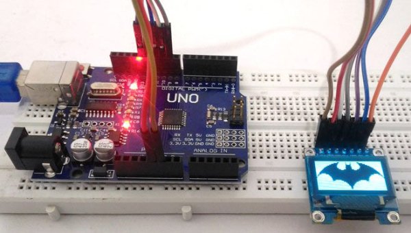
Simply load the image and adjust the settings to get your preferred preview of the image. Then click “Generate Code” copy the code and paste it into your Array. Upload the program and you are all done. I tried displaying a batman logo and this is how it turned out.
Read more: Interfacing SSD1306 OLED Display with Arduino