Flying model rockets is fun, but there is always the question of how high did it go. Using a programmable micro-controller and some sensors, you can monitor the entire phase of flight and measure acceleration and altitude, among other things. With this project, I’ll show you how I did just that, using off-the-shelf open source hardware and software to build an Arduino compatible flight telemetry system.
Model rocketry telemetry is nothing new. Amateurs have been stuffing electronics in rockets since the beginning of the hobby. A programmable micro-controller coupled with a low-power radio, however, allows us to take the hobby to a whole new level. What makes this project notable is:
– Wireless data transmission allowing in-flight monitoring or post-flight data downloading without the need to physically access the on-board hardware.
– Constructed from easily available open source hardware and software, allowing anyone with modest soldering and programing skills to put together a configuration to acquire and record any data they desire. No custom PCBs, chip programmers, or toolchains to setup as in my last well received, but little followed Instructable (http://www.instructables.com/id/Buggy-A-Crafty-Programmable-LED-Creature/)!
A 50 gram, on-board micro-controller collects pressure and acceleration data and then transmits it on 915 mHz using a Hope RM12 module at a rate of about 50 reading per second. A separate micro-controller connected to a laptop via USB receives the data and transfers it to a serial port. A software program running on the same computer graphically displays the data as it is collected, and also saves it to disk for further analysis. Piece of cake, right?
Step 1: Hardware
The heart of this system is an Arduino compatible JeeNode micro-controller designed by Jean-Claude Wippler from the Netherlands (http://jeelabs.org/ ). It contains an Atmel Atmega 328P, which has more memory and runs faster than my first computer (a Sinclair ZX-81). The JeeNode has a significantly smaller footprint than a standard Arduino, similar to Lady Ada’s Boarduino, but also has an integrated Hope RM12B wireless module. Additionally, the JeeNode has the I/O pins grouped in to four “Ports” to facilitate standardizing sensor connections, and runs at 3.3V. JeeLabs has developed a number of sensor/breakout boards, called “Plugs” using the IC2 interface, meaning they can be piggybacked on to the same port, making the JeeNode extremely extendable. In addition to the hardware, JeeLabs provides a software library making the use of ports and assessing sensor data very easy.
I used the following hardware, available in the U.S. from Modern Device (http://shop.moderndevice.com/ ) or elsewhere from JeeLabs (http://jeelabs.com/ ).
*JeeNode Kit ($22.50) (a.k.a. “Transmitter”)
*JeeLink Module ($36.50, assembled) (a.k.a. “Receiver”)
*JeeLabs Pressure Plug ($21.95) Bosch BMP085 barometric pressure and temperature sensor.
*USB BUB Board Kit ($14.00) or FTDI programming cable
Optional:
*JeeLabs Gravity Plug ($20.00) BMA020 3-axis accelerometer sensor
*JeeLabs Memory Plug ($9.50) (1 x 128KB STMicroelectronics M24M01 EEPROM)
For the full setup, you are in for about $125 + shipping. You could fly with just a Pressure Plug for altitude. You will also need batteries and a holder (I got mine at RadioShack). Consider this a small investment in your continuing Maker education. You only need one JeeLink and USB BUB. You can add or reuse as many JeeNodes as projects you dream up (or just type “Arduino” in the Instructables search box). The sensors and Port library can also be used with a standard Arduino with some effort.
Disclaimer:
I do not work for or have financial interest in JeeLabs. In fact, I would have a hard time pointing to the Netherlands on a map. I have, however, worked with Jean-Claude’s tech and find it well engineered, documented, and supported. Those are three requirements to get my hard earned money in my pursuit of hobby. I hope this sends more his way.
Makers Solder :
Each of the kits have instructions online and require some soldering. The sensors need headers soldered depending on how you position them. If you are unsure of your soldering skill, check out http://www.instructables.com/id/How-to-solder/ . If you want to see what building the kit involves, check out http://jeelabs.org/2010/09/26/assembling-the-jeenode-v5/ . Once you build this, you can definitely claim you can solder. Hacking is all about mad skills.
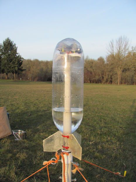
In my hardware configuration for the Transmitter, all the IC2 sensors are connected to Port 3, and I have a single LED and resistor hooked to the Port 4 digital & GND lines. Any variation from this layout can be easily accounted for in the Transmitter program by changing the Port numbers. I’m powering the JeeNode using 2 x AA in a plastic RadioShack battery holder. The flight assembly weighs in at about 50g, of which a little less than half is battery. A light-weight lithium ion battery would be ideal for this, but because of the near constant radio operation, it would take a bit more than a CR2032 coin cell (yes, I tried).
Step 2: Software
If you are already an Arduinoist, you are probably already have the Arduino programming environment installed. If not, head over to their website to get and install the software at (http://arduino.cc/en/Main/Software ). I’m using Arduino version 21.
In addition to the Arduino software, you need the JeeLabs “RF12” library available at http://jeelabs.net/projects/cafe/wiki/Libraries . You will also need the JeeLabs Port library modified to get the +-8g accelerometer settings attached below. Put them in the “arduino-00xx/libraries/ ” folder of your Arduino installation before launching the software. These are required for the provided programs to compile correctly prior to uploading them, and will also give you access to the example programs if you want to try out sensors individually.
To graph and save the data on the computer, I’m using Processing. It is based on the same underlying software as Arduino, but is geared to graphical output. The language and syntax is very similar, and if you’ve done either, picking up the other is quick and easy. It also has a lot of interesting example programs installed. Download Processing from (http://processing.org/download/ ). I’m using Processing version 1.0.9.
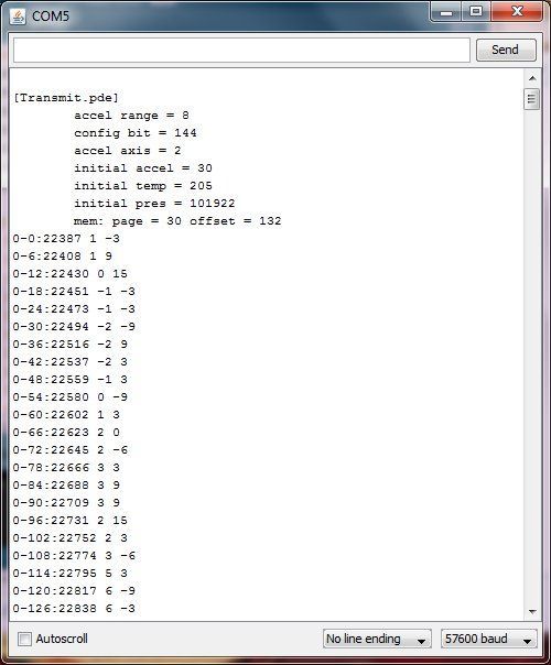
The final piece you need is the three programs, or “sketches” I’ve written, “Transmit.pde” uploaded to the on-board JeeNode to transmit data, “Receiver.pde” uploaded to the JeeLink receiver, and finally, “Graphing.pde” running in Processing on the computer. If you have questions about uploading or running sketches, head on over to the “Getting Started” pages at http://arduino.cc/en/Guide/HomePage for Arduino, or http://www.processing.org/learning/gettingstarted/ for Processing.
But wait, one more hoop to jump. I had to modify the JeeLab Ports library in order to get the +-8g function on the accelerometer.