We enjoy having an ordered, methodical and efficient lifestyle, however, more recently we have acquired a taste for the disorganized, topsy-turvy, chaotic lifestyle. Which is why, in this Instructable we attempt to address our new found love for chaos by building a simple machine to visualize the effects of chaos. We used the power of CAD and digital fabrication to create the parts however in later steps we provide alternative approaches in case you don’t have easy access to digital fabrication tools.
The entire system is made using off the shelf parts that can be bought easily.
Follow on to create your own Double Pendulum with which you can visualize the effects of chaos and do drop a vote for this project in the “Simple Machines Challenge” if you enjoyed the project and decide to build your own version. We would love to see your own versions so do post your creations using the “I made it” section.
Step 1: Overview of Pendulums and the Relation Between the Double Pendulum and Chaos
A simple pendulum is a simple machine that consists of three parts:
- The pivot
- The mass
- The link that connects the mass to the pivot
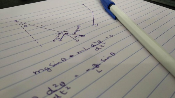
The pivot allows the pendulum to swing freely. The position in which the pendulum rests (when the mass is directly below the pivot) is called the equilibrium position. When the pendulum is pushed or nudged away from its equilibrium position, it is subjected to a restoring force due to gravity that will attempt to swing it back towards the equilibrium position. This causes the pendulum to oscillate back and forth about its equilibrium position. The motion of a simple pendulum can be easily described using a basic differential equation which is usually elaborated in high school physics courses.
However, when a second pivot is attached to the bottom of the pendulum and a second pendulum is attached to the bottom of the first pendulum, the dynamics of the double pendulum changes drastically and cannot be expressed using a simple differential equation any longer. The pendulum exhibits rich dynamical behavior and is chaotic.
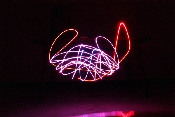
A system is considered chaotic when “minor changes” in initial conditions lead to “widely different outcomes“. A double pendulum is chaotic because when the initial force by which you nudge the pendulum or the angle by which you deviate the pendulum is varied slightly, the trajectory that the pendulum follows is completely different. This is what we would like to visualize in the course of this Instructable.
Step 2: Materials Needed
Here is the list of all the parts and tools required to make your very own Double Pendulum. All parts should be commonly available in local hardware stores or online.
Materials:
- 6 mm acrylic sheets
- 3D printer filament (color of your choice)
- Plank of wood (measurement are not critical)
- Cardboard
- Wood screws
- Skate bearings
Electronics
- NodeMCU x 1
- RGB LED x 1
- 9V battery x 1
- 9V battery clip x 1
- Perfboard
- Header pins
Tools
- Double sided tape
- Scissors
- Laser cutter (optional)
- 3D printer (optional)
Excluding the tools the total cost of this project is roughly 10$.
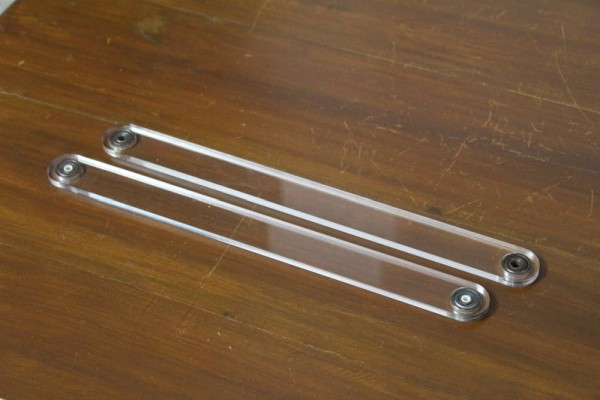
Step 3: Digitally Fabricated Parts
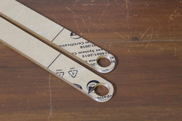
The parts required for this project had to be custom designed therefore a 3D printer and laser cutter were used to manufacture them. The print was made at 60% infill, 4 perimeters, 0.4mm nozzle, and a layer height of 0.1mm with PLA. The color is of your choice. You can find the complete list of parts below along with the STLs and design files to print your own version.
- Pendulum arm x 2
- Table mount x 1
Note: This step is optional since we provide alternative methods for creating your double pendulum that does not require 3D printers and laser cutters.
Step 4: Assembling the Pendulum Arms
If you have laser cut the pendulum arms skip to the next paragraph. For those who don’t have access to a laser cutter, you can print the design of the arm from the previous step and use it as a reference to cut out the shape using cardboard. We recommend you to stick the printout onto a sturdy piece of cardboard and use an X-acto knife to cute the shape out. Repeat this twice to make two arms.
Once you have the pendulum arms, push a bearing into each of the four holes. Bearings are crucial for this project since any resistance while the pendulum swings will cause the swing to decay more rapidly. The fit should be snug, but we recommend a drop of glue to secure the bearing in place.
Next, join the two arms using a bolt and a nut. A thin spacer is required between the two arms.
Step 5: Mounting the Pendulum
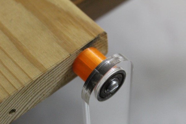
There are two ways you can mount the pendulum. If you have access to a 3D printer, print the table mount piece provided in Step 3, which you can use to mount the pendulum arm to a table. Use a bolt to attach one end of the double pendulum to the 3D print and secure it in place using a nut. The table mount can then be attached to the table using some weights or double sided tape.
In case you don’t have access to a 3D printer, the pendulum can be mounted to a large plank of wood, which can then be secured to the table using clamps or weights. Drill a pilot hole into one end of the plank and attach the pendulum to the plank using a wood screw. Remember to add a spacer between the plank of wood and pendulum. Finally hold the plank of wood in place using weights or a clamp.
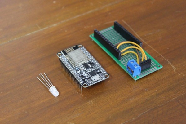
Step 6: Electronics Module
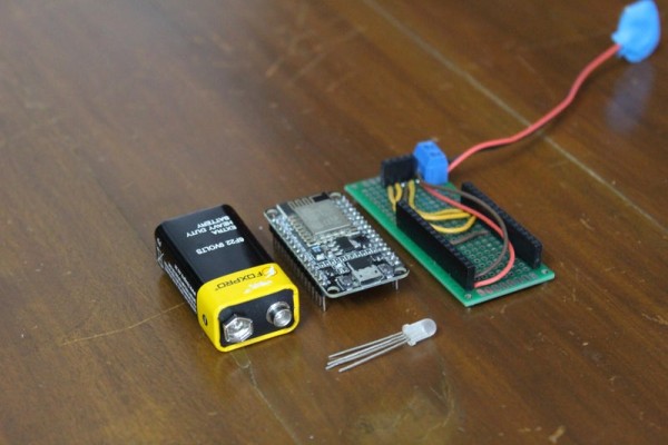
The electronics module is the most critical aspect of the project. It will eventually allow us to visualize the chaos in a double pendulum system. The electronics modules consists of 3 parts:
- the microcontroller, NodeMCU in our case
- the led light, a regular RGB led in our case
- the power supply, a regular 9V battery
Since we wanted the electronics to remain contained, without any extra wires that could potentially tangle and ruin the system, we decided to created a DIY PCB using some perfboard.
To build the PCB, cut the perfboard to length, such that the width of the NodeMCU fits. Next, solder some female header pins along the two edges where you will eventually mount the NodeMCU. Towards the bottom of the PCB, solder 4 more female header pins which will hold the RGB LED. Finally solder a screw terminal on one of the sides, which will be used to power the microcontroller and LED using the 9V battery. Once all the pieces are soldered, you can begin to wire the parts together using the following table:
LED to NodeMCU
Make sure to use a common cathode RGB LED, otherwise this system will not work.
- LED GND to NodeMCU GND
- LED Red to NodeMCU GPIO5
- LED Green to NodeMCU GPIO0
- LED Blue to NodeMCU GPIO4
Power port to NodeMCU
- Power port -ve to NodeMCU GND
- Power port +ve to NodeMCU Vin
Once the wiring is complete, simply connect the battery and make sure the NodeMCU powers on. Use double sided tape to hold the battery to the back of the PCB and use some more double sided tape to secure the module to the pendulum arm.
Step 7: Programming and Controlling the Electronics Module
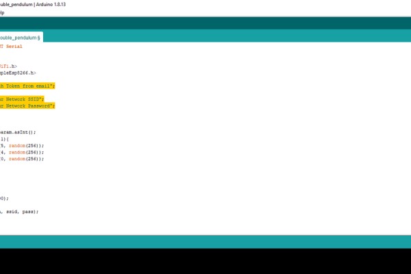
To use the program attached below you will need to download an additional library in the Arduino IDE. Open up the Arduino IDE and go to Sketch => Include Library => Manage Libraries and search for “Blynk” in the search box. Once the library appears, click the install button.
Before uploading the Arduino sketch you need to build the Blynk app. Begin by downloading the Blynk app on your phone using the Android’s Google Play Store or Apple’s App Store. Once the app is installed, open it (they might prompt you to create an account) and click on the “+” icon to create a new app and name it whatever you want. Once you create the app you will receive an email with an authorization token, note it down since it will come in use later. Drag three sliders and once button onto the screen. Map the three sliders to the digital pins, 5, 0, and 4 and rename them to R, G, and B respectively and map the button to the virtual pin 0.
Once you have built the app on Blynk, open up the Arduino sketch attached below and modify the following lines:
- Replace “Auth Token from email” on line 7 to the authorization token you received in your email
- Replace “Your Network SSID” on line 9 to your wifi network’s SSID
- Replace “Your Network Password” on line 10 to your wifi network’s password
Once you have made the necessary changes, upload the program to the NodeMCU.
Test the program by running the app using the triangular button in the top right corner of the app and slide the sliders and the color of the RGB LED should change accordingly. The button can be used to create a randomized color every time you press it.
Step 8: Setting Up the Camera
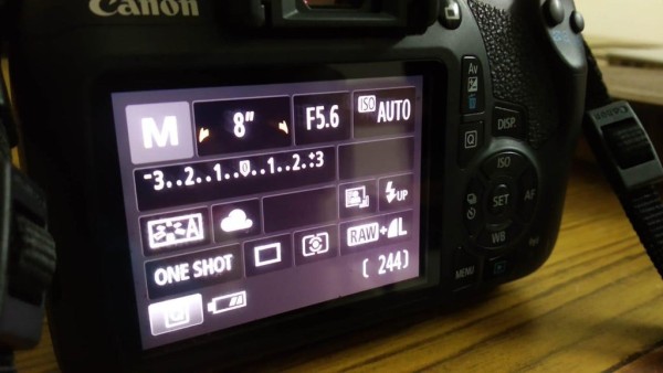
To take long exposure stills of the double pendulum in action, make sure to shoot in a dark environment. Begin by setting your camera in manual mode. Then use the following settings:
- Set the aperture to the lowest value
- Set the shutter speed to 8 to 15 seconds
The rest of the settings can remain as they are or can be set to auto. While taking the pictures it might help to have two people, one person to take the shot while the other person releases the pendulum. In case you are alone, use the self timer option on your camera to take the still while you get ready to release the pendulum.
Source: Visualizing Chaos With the Double Pendulum