
The Riding Through Walls: Google Street View Stationary Bike Interface allows you to cycle through Google Street-View from the comfort of your living room. Using some simple electronics, an Arduino, a stationary bike, a computer, and projector or TV you can explore the world without leaving home. See http://ridingthroughwalls.megansmith.ca/ for more information.
Step 1: Materials
Parts List
- Door Sensor/Reed Switch (Adafruit ID375, Sparkfun COM-13247, Digikey COM-13247)
- 1 or 2 Magnets (Adafruit ID9, Sparkfun COM-08890)
- 2 Pushbuttons (Adafruit ID471, Adafruit ID1505, Sparkfun COM-09337, Sparkfun COM-11967, Sparkfun COM-11994, Digikey COM-09337)
- Wire 7.62 m (25 ft) (Adafruit ID290/ID2984,Sparkfun COM-08022/COM-08026, Digikey PRT-08022/PRT-08026)
- Optional Quick connects (Adafruit ID1152, Digikey WM13557-ND, or Digikey A108294CT-ND for smaller connectors)
- 2 Tube Clamps
- Zip-Ties or Velcro trips
- Heat shrink (Adafruit ID344)
- Arduino Leonardo, Due, Micro, or Zero (required for Human Interface Device capability)
Materials for Assembly
- Wire cutters
- Needle nose pliers
- Soldering Iron (optional)
- Flux Core Solder (optional)
- Electrical Tape (optional)
- Heat gun or lighter
Equipment Needed For Use Stationary bike
- Computer with USB and monitor output
- Projector or Monitor
Step 2: Prepare Your Space
This project is meant to allow you to explore the world by bike from the comfort of your living room. For best results use with a projector that covers the entire wall with the projected image. TVs and monitors will work as well, but the larger the image, the better the immersion. Place your stationary bike at a reasonable distance from the image, as close to centered as possible.
With an idea of where you want to place all your components you can now run the wires from the buttons and reed switch to the Arduino to get an estimate of how long your wires actually need to be.
Step 3: Circuit
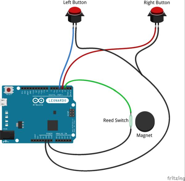
The Riding Through Walls Google Street View Bike uses a relatively simple circuit consisting of two pushbuttons and one reed switch connected from the Arduino’s inputs to ground. The internal pullup resistors are used avoiding the need to build the circuit with external resistors. The circuit shown has been tested with the Arduino Leonardo and should work for any Arduino.
- Magnetic reed switch attached from pin 2 to ground
- Right pushbutton attached from pin 3 to ground
- Left pushbutton attached from pin 4 to ground
- Internal pullup resistors used for all three pins
NOTE: As the circuit relies on the Arduino’s internal resistors please take extra caution as setting the connections to OUTPUT HIGH could short 5V to ground and permanently damage the Arduino.
Step 4: Build Buttons
Run two lengths of wire from the Arduino to each of the handlebar pushbuttons. Cut the wire to length and crimp on the quick-disconnects to the end which will attach to the button. If you prefer the wire can be soldered to the buttons instead.
Step 5: Install Buttons for Turning
Depending on the size and shape of your handlebars there are a number of ways to attach your push buttons. You’ll want them easily accessible and close to your hands.
Temporary or Flexible Solution: Using Tape or Velcro strips
- Use Velcro strips or a strong but flexible tape such as electrical tape, hockey tape, or gaffer tape.
- Hold the button in place perpendicular to the handlebar.
- Wrap the velcro/tape around both the button and handlebar, making an X-shaped pattern to prevent the button from rotating.
Permanent Solution: Using standard handlebar
- Drill a hole the same diameter as your button and thread the wires so that your button can be inserted into the handlebar at a comfortable distance for your thumbs to operate them while holding your handlebars.
Step 6: Attach Arduino to the Bike
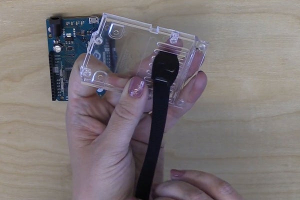
To attach the Arduino Leonardo to the bike use the plastic mount provided with the Arudino.
- Run a Velcro strip through the vertical grating on the mount.
- Loop the Velcro around the bike where you would like to attach it.
- Insert the Arduino into the mount by pressing it into place.
If you do not have the plastic mount that comes with the Arduino there are other ways to make a case and locations to store the system safely.
Handlebar/saddle bag
You can simply place the Arduino in a handlebar or saddle bag to keep it secure and protected. The bag is designed to be easily attached to most bikes
Basket
If your bike has a basket you can place the Arduino in the basket and cover with a protective surface such as a plastic sheet or wooden board.
Reusable Plastic Container
You can also use a reusable plastic container. A small Ziploc or Tupperware container should also do the trick. Simply cut or drill holes in the base of the container to run zip ties through, and one hole to run the wires through. Zip tie the container to the bike and place the lid on when the Arduino is installed.
3D Printed Case
There are a number of 3D printed cases that you can be download and printed from sites such as Thingiverse including this one for Arduino Uno and Leonardo. You may want to modify the case before printing to suit your mounting solution, for example making holes to run zip ties through the case. Simply 3D print the case, assemble it, and zip tie or tape it to the bike.
Step 7: Install Reed Switch and Magnet
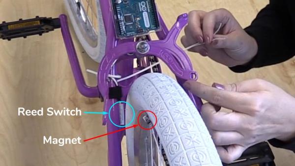
First, the reed switch and corresponding magnet need to be installed on the wheel and frame. Depending on the type of drive system your stationary bike uses you will need to take a slightly different approach, but in each case the magnet goes on the moving part and the reed switch goes on the frame. They should be mounted in a location where they won’t interfere with any other parts such as brakes or drivetrain components. If the wires attached to the reed switch aren’t long enough you’ll need to solder more wire to extend them.
Alternative 1 – Bike Wheel With Tire
If you’re using a regular bike on a bike trainer, or one of many older stationary bikes that use a standard bike wheel and tire then these steps are for you.
- Try placing the magnet directly on the wheel. If the wheel is steel then the magnet will hold itself in place.
- If the magnet does not stay in place it can be attached to the wheel using double sided mounting tape, hot glue or super glue.
- Alternately a second magnet can be placed inside the rim to hold the magnet to the wheel. To accomplish this follow these steps:
- Remove the wheel from the bike as this will make the following steps easier.
- Deflate the tire by removing the dust cap and pressing the valve in with a screwdriver, pen or other small tool.
- Pull the tire back from the rim where you’d like to install the magnet.
- Place one magnet inside the rim, offset towards one side of the wheel. Place the other magnet on the outside of the rim in the same location. The magnets should hold each other in place.
- Re-inflate the tire using a bike pump or air compressor, be sure not to exceed the recommended pressure printed on the side of the tire.
- Re-install the wheel on the bike.
- Install the Reed Switch on the frame within 12 mm (0.5″) of the magnet while keeping it clear of any moving parts. Make sure that the larger side of the reed switch is facing the magnet. Use zip-ties, velcro strips, tape, or hot glue to secure it in place.
Alternative 2 – Exercise Bike with Flywheel
Most modern exercise bikes use a compact flywheel of some kind in place of the wheel. In this case you will have to use double sided mounting tape or glue as there is no way to secure the magnet with a second magnet.
- Find a mounting location for the magnet which won’t interfere with any brake, frame or drive train components.
- Attach the magnet to the flywheel using double-sided tape, hot glue, or super glue.
- Install the Reed Switch on the frame within 12 mm (0.5″) of the magnet while keeping it clear of any moving parts. Use zip-ties, velcro strips, tape, or hot glue to secure it in place.
Alternative 3 – Exercise Bike with Fan
Some stationary bikes use a fan for resistance, in this case you can attach the magnet to the end of a fan blade.
- Remove fan housing from bike.
- Attach magnet on fan blade using a second magnet on the other side of the fan blade, double-sided tape or hot glue.
- Mount as close to fan housing as possible.
- Re-install fan housing.If using a fan style stationary bike you can likely place the reed switch directly on the fan housing.
- Install the Reed Switch on the frame or housing within 12 mm (0.5″) of the magnet while keeping it clear of any moving parts. Use zip-ties, velcro strips, tape, or hot glue to secure it in place.
Alternative 4 – Crank Mount
If none of the previous methods will work for you, or if you’re concerned about disassembling your bike then this method will work as a last resort. Note that your speed will be fixed regardless of what gear or resistance you are using.
- Install the magnet onto the inside of the crank arm using double-sided tape or hot glue. Be sure to avoid installing on the pedal pivot or too close to the crankshaft.
- Install the Reed Switch on the frame within 12 mm (0.5″) of the magnet while keeping it clear of any moving parts. Use zip-ties, velcro strips, tape, or hot glue to secure it in place.
Step 8: Test Reed Switch
- Be sure to verify that nothing hits either part, and that they do not interfere with the normal operation of the bike!
- Once the magnet and reed switch are installed you can verify operation using a circuit tester or multimeter. The switch should be normally open, closing briefly when the magnet passes by the reed switch.
- If using a multimeter the resistance between the switches should be “infinite” except when the magnet is near the reed switch, in which case it should be as close to 0 as possible.
Source: Riding Through Walls: Google Street View Stationary Bike Interface