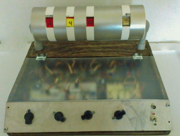
This is a 4 band Mechanical Color Code Resistor Calculator, The idea of making this Mechanical Resistor came when I accidentally dropped my box of resistors and all resistors (1300 of them) got mixed up. ooops! . Thank god there’s an APP for that, So while picking them up (the resistors) and soaring them out I was thinking, how cool would it be to have a big resistor that you can actually manually rotate the bands and get the resistor value right away. If you are into electronics and you are really passionate about it like me, you’re always looking for projects and challenges to take on all the time. So, with that idea and a vision in mind I started working on my new project, of course with the help of Arduino UNO microcontroller.
HOW DOES IT WORKS?
There are 4 small stepper motors , 4 stepper motor drivers, 4 10K potentiometers and 2 Arduino UNO on a breadboard. As you turn the potentiometer, the motors rotate displaying a color and a value at the same time.
Step 1: Material List
SP = www.sparkfun.com , YD = www.yourduino.com , J = www.jameco.com , HP = Home Depot
ARDUINO UNO ON A BREADBOARD COMPONENTS LIST ( J )
At Mega 328p with arduino UNO boot loader
5v Voltage Regulator 7805-T
LED (2 red ) and (2 green)
resistor 1/4 w, 10k and 180 ohms
Radial Capacitor 10uf 50v
Ceramic Capacitor disc 22pf 50v
ceramic Capacitor disc 0.1uf 50v
Tantalum Capacitor 10uf 25v
16Mhz Crystal low-profile
Pushbutton switch, off/on
Stepper Motor with driver board (YD)
Blue LED light (YD)
Panel mount LED holder 5mm (YD)
DPDT On /OFF switch (YD)
10k small Potentiometer (YD)
10k Potentiometer chicken head Knob (SP)
9v Battery holder (Pack of two) (YD)
9v Battery (YD)
6v, AA Battery case (YD)
AA Battery (pack of 4) (YD)
40pin flat cable female ends (YD)
Breadboard jumper kit (YD)
Breadboard 16cm with power and Grd busses (YD)
Breadboard 8cm with power and Grd busses (YD)
Mini Digital Voltmeter 0-30v dc (red) (YD)
Hook-up wire, solid (black, Red & Green) (SP)
solder tube .031 Inch Dia. (SP)
Liquid Tape 4FL. OZ (HD)
Servo Mounts (SP)
Screw-Phillips head (1/2″, 4-40, 10-pack) (SP)
Nut metal (4-40, 10-pack) (SP)
wood screws #6 x 3/4″ pan head Phillips (HD)
11/32″, 2′ x 2′ Plywood sheet (HD)
MINWAX wood finish stain (provincial 211) (HD)
Primer spray paint (HD)
Gold spray paint (HD)
1/8″ Plexiglas 11″ x 14″ (HD)
Compressed wood (HD)
Narrow utility hinges 1″ (HD)
1/2″ x 2′ PVC pipe (HD)
1/2″ PVC 90* elbow (HD)
1/2″ PVC coupling (HD)
2″ PVC pipe Blocker (HD)
2″ x 2′ PVC pipe (HD)
3″ PVC pipe Blocker (HD)
3″ x 2′ PVC pipe (HD)
Nailed metal bridging (HD)
4″ (10cm) Cable Ties (HD)
Step 2: Building the Enclosure
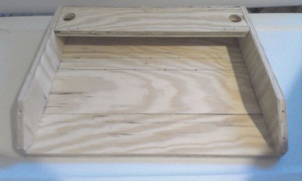
Start by cutting the six pieces that make the enclosure, the first piece would be the base (bottom piece).
1) Grab the 11/32″, 2′ x 2′ Plywood sheet and cut a 14″ x 11″ piece.
2) Cut the side pieces, (see 2nd picture) for measurements.
3) Cut a 13 1/8″ x 2″ piece, this is the back part of the enclosure. (See 4th picture)
4) Cut a 13 1/8 x 2 1/2 piece, and drill two 1″ hole on each side. This is the top piece of the enclosure.
(see 5th picture) for measurements.
5) Put the enclosure together, use the #6 x 3/4″ wood screws.
6) After the enclosure is been assembled, is time to sand and stain the enclosure. (pix 6)
Step 3: Front Panel
Cut a 14″ x 2 1/2 ” piece of the compressed wood, and drill 6 1/4″ holes for the pots. You may have to check the drill bit size for the LED holder and switch. Depending of what LED holder and switch you get.
(see 2nd picture). Next paint the panel and let it dry before installing the pots, LED and switch.
(see 3rd picture) for measurements.
Next cut (16) 12″ long of hook up wire, solder each wire to each potentiometer terminal, the LED and the switch. Make sure you use electrical liquid tape or shrinking tube to cover the splices. (see last pictures). Last screw the panel to the enclosure.
Step 4: Motors support bracket and side posts
Grab the nailed metal bridging bracket and put a line across on each end , right where the curved shape ends (see 1st picture). Measure 1/2″ from the first line put a 2nd mark across, then make a 3rd line across 1/2″. First bend the bracket 45* on the first line, then make a second 45* bend on the second line. Do it to both sides. (see picture 2,3,4,5).
Next cut the bracket in half, and place on piece on top of each other and tape them together, it should measure 9″ from side to side (see picture 6,7,8,9). Last drill two holes on both ends of the bracket (see picture 10,11) and cut the rest of the end of the bracket at the 3rd line across it .
Now we are going to work on the side posts (PVC pipes)that hold the motors support bracket.
cut (2) 2 1/2″ of 1/2″ PVC pipe, and place the 1/2 ” elbow on one side and the coupling on the other. (see picture 12,13,14) Once both pieces assembled is time to paint them. (I used automotive primer spray)
While the two posts are drying get the (2) 3″ PVC pipe blocker and place them back to back together and drill a 7/8″ hole in the center on both pieces at the same time, so you’ll have the center holes of both blocker matching each other and will make the motor support bracket level without any more adjustments to make. Last test fit the posts make sure they fit on the enclosure and through the 3″ PVC pipe blockers. Do not glue them together at this point. See pictures 15 – 22.
Step 5: Mounting and making the motors base
Now we’re going to cut a 9 1/2″ piece of Plexiglas this is the stepper motor base and drill (8) 3/16″ holes (see picture 2,3,4) for measurements. Start by bolting the servo mounts from sparkfun to the stepper motors using the 1/2″,4-40 bolts and nuts. Now place the motor on top of the Plexiglas aligning the rear motor mount with the holes previously drilled. Now mark the rest of the motor mount holes and drill them with a 3/16″ bit (see picture 5,6,7,8). bolt them down and use 2 #6 flat washers on each hole of the motor mounts (see picture 9,10,11). Now place and center the Plexiglas piece on the motor bracket and drill (2) 3/16″ holes through the Plexiglas onto the bracket, one on each side about 2″ from each end (see picture 12,13,14,15)and bolt them together using 1/2″,4-40 bolts and nuts. finally get the motor support bracket and bolt it to the 3″ blocker with the 1/2″, 4-40 bolts and nuts. 2 per side, as close as you can to the opening in the middle (see pictures 16,17). Now place the posts on the enclosure (see last pictures).
Step 6: Making and Mounting the wheels (bands)
For this step you will need:
• 2″ PVC Pipe
• 2″ Knock out plug (4)
• 1/4″ drill bit
• Label roll
• Color sharpies (black, brown, red, orange, yellow, green, blue, violet).
• A utility knife Glue stick.
Cut (4) 3/4″ thick piece of 2″ PVC Pipe (see picture 1,2,3). Next drill a 1/4″ hole in the center of the knock out plugs. Place 2 knock out plugs together back to back and drill a 1/4″ hole through both of the pieces. Make sure these holes a centered to the knock out plugs. Do the same for the other two plugs
(see picture 4,5,6). Get (4) binding post and cut 1/4″ off the top (see picture 7,8), now place the knock out plug on the 2″ , 3/4″ thick PVC piece and the post through the knock out plug. do not glue jet, this is just to test to fit step (see picture 9,10).
Pull out 4 piece long , 8 1/2″ off label roll, and draw a line across every 3/4″ , you should end up with (11) 3/4″ sections per piece (see picture 11,12,13). Now put a light coat of stick glue on each band ( I am going to refer to the 2″, 3/4″ thick PVC Pipe as bands from now on) and wrap the 8 1/4″ label piece around each band, you end up over lapping the last section onto the first one see picture 14,15,16). Grab the utility knife and trim the label as close as you can to the band’s outer edge (see picture 17,18).
Now time to color the bands, grab two bands, color and number them in this order:
• BLACK 0 (use a white or silver sharpie to number the black section)
• BROWN 1
• RED 2
• ORANGE 3
• YELLOW 4
• GREEN 5
• BLUE 6
• VIOLET 7
• GRAY 8
• WHITE 9
The Gray section was colored using a #2 pencil, go over the section with a very light pressure.
Color the 3rd band (The multiplier) and number them as follow:
• BLACK (Do not number this section)
• BROWN 0
• RED 00
• ORANGE 1K
• YELLOW 10K
• GREEN 100K
• BLUE 1M
• VIOLET 10M
• GOLD 0.1
• SILVER 0.01
The 4th band is the tolerance in percentage, color and number as follow:
• BROWN 1%
• RED 2%
• GREEN 0.5%
• BLUE 0.25%
• VIOLET 0.1%
• GRAY 0.05%
• GOLD 5%
• SILVER 10%
• last section do not color just write the word “plain” an number it 20% under the word plain.
See picture 19,20) and see last picture, is the chart with the color and values of each band, and I purposely taped off one section so it won’t confuse you, you don’t need that section. That section is for a 5-band resistor.
Step 7: Wiring the small stepper motors
Time for the fun part. You are going to extend the wires of the motors so they can reach the motor driver boards down in the enclosure. Grab the Cat5e and cut (4) 12″ long sections and peel the jacket off, exposing the conductor inside. now grab 5 of those conductors and label each wire on both ends as follow:
• BLUE (1st wire)
• PINK (2nd wire)
• YELLOW (3rd wire)
• ORANGE (4th wire)
• RED (5th wire)
now, cut off the connector of each motor at about 3 1/2″ away from the connector. Take the one end of the labeled Cat5e and solder each wire to the wires on the motor to their corresponding color. Cover the splices with shrink tube or liquid electrical tape. Do the same to the rest of the stepper motors.
Once all the motor’s wires had been soldered and covered, tape each motor wires together and label them motor 1, motor 2, motor 3 and motor 4. Run the other end of the wires down into the enclosure through the side post one by one. Make sure you label each bundle, 2 set of wires per side post. Now save the stepper motor connectors, you’ll need them to plug them into the driver boars later. Once done with the wiring, install the band on each motor, just slide he the bands on the motor shaft.
See pictures for reference.
For more detail: Resistor Color Code Calculator with Arduino