
Summary of Rally Gearshift Display
A compact gearshift display for rally cars uses a small potentiometer on the main axis to detect gears. Due to vibration and 360-degree rotation issues between reverse and 5th gear, the device requires a calibration routine activated by a jumper. This routine records all gear positions to EEPROM for accurate mapping. The system features a bright LED display and custom firmware available as an Arduino project.
Parts used in the Rally Gearshift Display:
- Small potentiometer
- Main axis of mechanical sequential gearshift
- Large bright LED display
- Jumper switch
- Microcontroller board with EEPROM
- Arduino IDE firmware
This device was built at Recursive Software Development Labs in order to be mounted on a rally car competing in the Estonian National Rally championship.
The racing team needed help realizing a reliable measurement device which would output the currently inserted gear on a large, bright led display.
The biggest challenge to overcome was that the existing mechanical sequential gearshift would only allow enough room for a small potentiometer to be attached to its main axis, but the mounting mechanism is highly subject to vibrations, therefore after some time the readings would become unreliable or jittery.
Another problem was that when shifting from R until the 5th gear, the potentiometer would output identical readings both for R and 5 (as in, the axis would turn 360 degrees), making the first and the last gear undistinguishable.
This required to implement a dedicated calibration procedure, which is activated by switching oen jumper on the board.
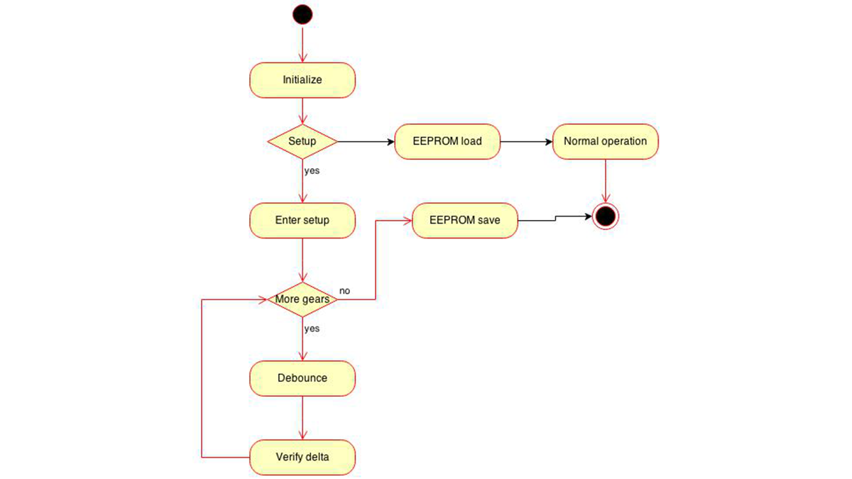
Whenever the jumper is set, a calibration routine is started, which requires the driver to put all the gears, in no particular order, in sequence. The firmware takes care of sorting out the correspondences of the various readings with the inserted gear, and then stores the new values in the EEPROM.
The general firmware behavior is:
The firmware to operate the device can be downloaded from here as an Arduino IDE project:
For more detail: Rally Gearshift Display
- Why was a special mounting mechanism needed?
The existing mechanism is highly subject to vibrations which cause unreliable or jittery readings over time. - How does the device distinguish between Reverse and 5th gear?
It uses a dedicated calibration procedure that sorts out correspondences of various readings stored in the EEPROM. - What triggers the calibration routine?
Switching on a specific jumper on the board activates the calibration routine. - Does the driver need to follow a specific order during calibration?
No, the driver must put all gears in sequence but not in any particular order. - Where are the new gear values stored after calibration?
The firmware stores the new values in the EEPROM. - Can I download the firmware for this project?
Yes, the firmware can be downloaded as an Arduino IDE project from the provided link. - What type of gearshift does this device support?
The device supports an existing mechanical sequential gearshift.
