Summary of Music PlayBox – ITTT
This project is a DIY "If This Then That" music box designed to simplify learning instruments. It allows users to select between piano or guitar and play specific chords via buttons, with status shown on multiple displays. The build involves laser-cutting an MDF case, soldering components like OLEDs and an MP3 module, and programming an Arduino Uno R3 to manage audio playback and display updates through an I2C multiplexer.
Parts used in the Music PlayBox:
- Arduino Uno R3
- Small Sized Powerbank
- Laser Cutted 3mm MDF Box (MakerCase.com)
- 1k Ohm Resistor
- YX5200 DFPlayer Mini MP3 Module
- TCA9548A I2C Multiplexer
- 2 x 8 cm Experiment Print (Islands)
- Jumper Cables
- 20 cm Tinned Cables
- 3 x 0.96 Inch OLED 128 x 64 pixels I2C Display
- 1602 LCD I2C Display
- Small Wooden Planks
- 3W 40mm Speaker
- Rotary Encoder KY-040
- 3x Mini Pressure Switch
- Piano Hinge
- Screws / Bolts / Nails
HKU Assignment
Welcome to my “If This Then That” Project.
For this project I made a simple music box where you can play several chords of instruments. You can choose which instrument you want to play (piano/guitar) and which chord you want to play per button.
In this instructable I will show you my concept, iterations and a short reflection. I will also share an electronic scheme and the code with explanation.
Supplies
- Arduino Uno R3
- Small Sized Powerbank
- Laser Cutted 3mm MDF Box (MakerCase.com)
- 1k Ohm Resistor
- YX5200 DFPlayer Mini MP3 Module
- TCA9548A I2C Multiplexer
- 2 x 8 cm Experiment Print (Islands)
- Jumper Cables
- 20 cm Tinned Cables
- 3 x 0.96 Inch OLED 128 x 64 pixels I2C Display
- 1602 LCD I2C Display
- Small Wooden Planks
- 3W 40mm Speaker
- Rotary Encoder KY-040
- 3x Mini Pressure Switch
- Piano Hinge
- Screws / Bolts / Nails
Step 1: Concept
For me brainstorming always takes way too long, so I wanted to make it easy for me this time. The first thing I decided was what purpose it has. I wanted to make something that solves a common problem. In this case the problem that learning an instrument can be quite difficult and that it potentially scares people away from making music. If I could solve this problem by simply making a tool/device that makes it easy to make music, it could mean a lot for those people.
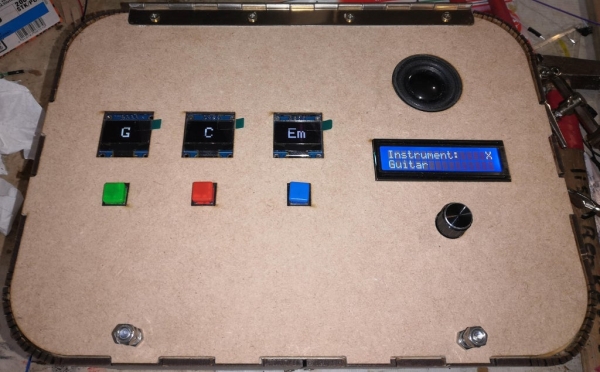
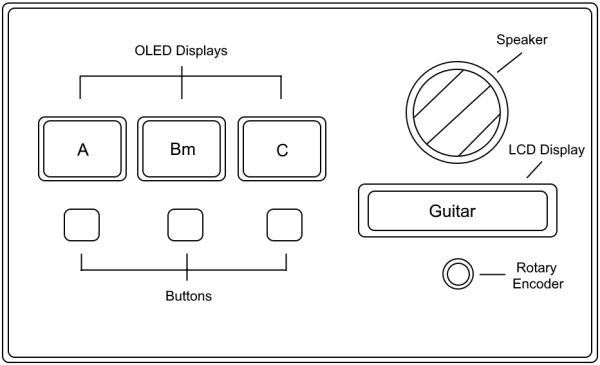
With this purpose I also figured that I really wanted to make something that plays music. Thus making the brainstorming a lot easier and more focused for me. And so I started drawing something that makes it easy for people to play any chord with any instrument they want. The result is a device that has in this case four display. Three for displaying the chords and one for displaying the instrument. The music would be played through a small speaker and you can play the chords with the buttons under the displays.
The device has to be easy-to-view so that people don’t get confused. Meaning that the amount of buttons has to be limited, only the essential should be present, in this case a volume switch, buttons to change the instrument and an on/off switch.
Step 2: Working With an LCD Display
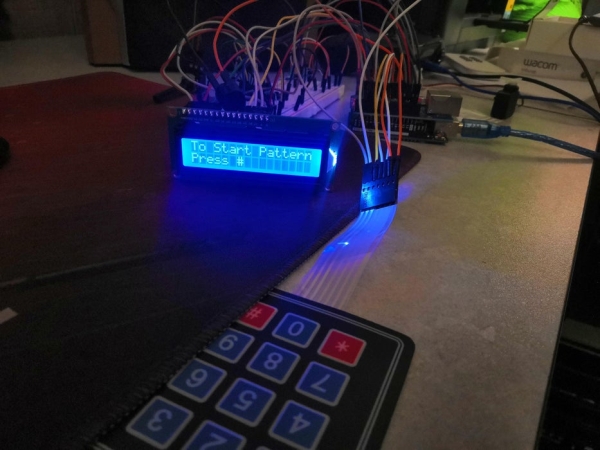
The LCD Display is an important component of the device. It shows important information such as the volume and instrument. That’s why it was important for me to get familiar with it. I’ve set up a simple system, where you have to enter a pattern with a keypad. The display gives you feedback on whether it’s correct or incorrect.
Step 3: The MP3 Module
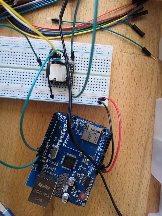
Boy oh boy… What a drama was this little thing. At first for a very long time it would never work, it would always give me the error to check the connection or sd card, not knowing that using an usb extender doesn’t work well with the serial communication of the arduino… So after a while I figured, let’s try if it works if I connect the arduino to the usb port directly and all of the sudden I got sound. After that I started figuring out how to make it work with buttons and play from different folders.
Step 4: Triple OLED Displays
The OLED Displays can also be considered as one of the most essential components of this device. To make it easy for myself I first connected one display. This was easy to set up following a few tutorials, but this quickly changed when I wanted to connect two more displays. After a lot of reading I found that two displays were no problem, because you could change the address of one, so that they are individually controllable. But whenever you need more than two of the same displays, things start to get tricky… The most simple solution was to get a multiplexer. After connecting that to the arduino I was able to connect up to eight displays.
Everything went well in the begining with all three of them displaying some simple centered text. But after I added more functionality to my device things started to get weird. Suddenly one of the displays started to not display anything anymore, and sometimes it did display something. After a lot of rewriting code and debugging my teacher finally found the solution. I was running out of SRAM that my displays needed. So after optimizing the code by changing ints to int8_t and writing serial prints to the flash memory, things started working again! Yay.
Step 5: Laser Cut Design
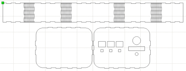
After everything was working I had to make a design for the case. For that I first measured all my components and offsets to get a total size for the length, height and depth. After that I made cut holes for all the displays, buttons, speaker and the rotary encoder. These had to be measured in mm to ensure perfect fit. The first cut that I did was on a thrown away piece of MDF, to see if my measurements were correct. And luckely I did that, because my measurements for the oled displays and the rotary encoder were wrong.
Step 6: Box Assembly
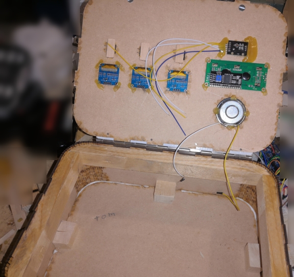
The next step was to assemble the box, this was done by screwing little square wooden planks on each side at the bottom to keep it attached. The next step was to make it able to open/close, because of the support at the bottom, the top wasn’t alligned, so that had to be fixed. This was fixed by adding rounded wooden planks at the top on each side. This way the side panels matched the position of the top panel, so that it could easily close. The top panel fitted more easily by polishing the stair construction on the top of the side panels. To round this step up, I added a pianohinge and some glue on the edges.
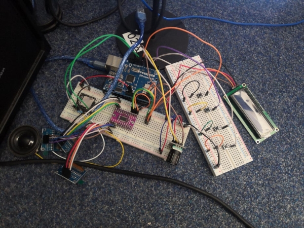
Step 7: Component Assembly
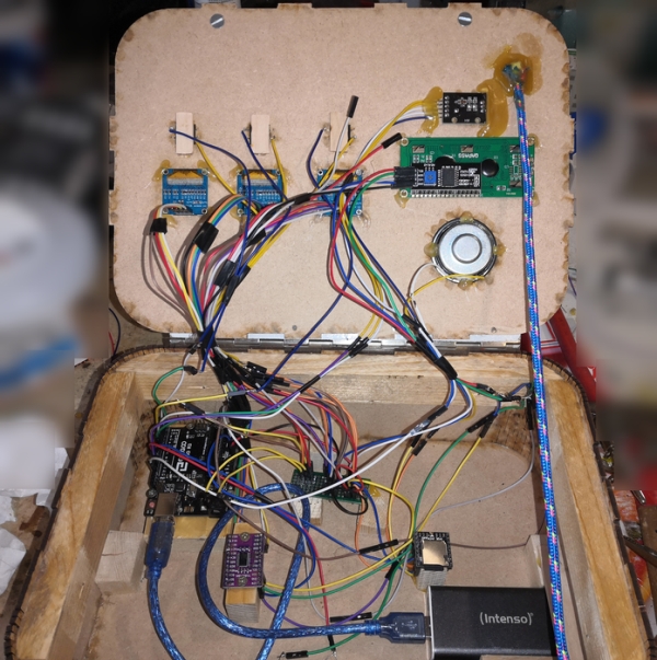
This was undoubtedly the most difficult part. From the soldering to cable management, everything was a mess. I started by the most easy part, adding cables to all the displays, the rotary encoder and the speaker. Hereby the speaker, rotary encoder and the button’s cabled had to be soldered. Luckely these were relatively easy compared to the rest. After this the experiment print had to be soldered. Luckely I bought a few of these, because I had no idea of how to use them.
When I bought them, I thought they were in rows, meaning that the whole row will be connected, but it turned out to be islands, meaning that every single hole is individual. So when I soldered 5v to a row, I had no power on any component, making me stress out because I didn’t know what to do. After some calls with people who knew what this component was, I found out that it was a island print and that I had to connect the holes with each other by connecting it with soldering tin.
From this point on things started to work again and I could finally finish the soldering. After the soldering it was time to decide where to screw and glue all the components and to make it easy to open/close without cables being stuck. And to round it up I glued a small rope to make it stay open.
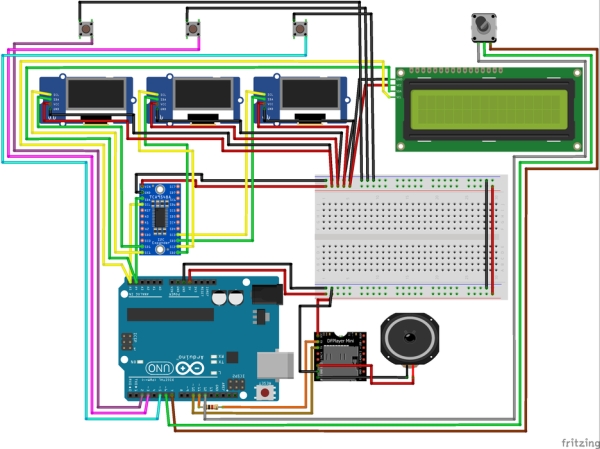
Step 8: Circuit
Step 9: The Code Part 1
#include <LiquidCrystal_I2C.h>
#include <Wire.h>
#include <PinButton.h>
#include <Adafruit_GFX.h>
#include <Adafruit_SSD1306.h>
#include "DFRobotDFPlayerMini.h"
#include "SoftwareSerial.h"
#include "TCA9548A.h"
#define SCREEN_WIDTH 128
#define SCREEN_HEIGHT 64
#define SCREEN_ADDRESS 0x3C
#define OLED_RESET -1
#define encoderA 12
#define encoderB 7
#define encoderButtonPin 6
#define playButton1 2
#define playButton2 3
#define playButton3 5
SoftwareSerial mySoftwareSerial(10, 11); // RX, TX
DFRobotDFPlayerMini myDFPlayer;
LiquidCrystal_I2C lcd = LiquidCrystal_I2C(0x27, 16, 2);
Adafruit_SSD1306 display1(SCREEN_WIDTH, SCREEN_HEIGHT, &Wire, OLED_RESET);
PinButton encoderButton(encoderButtonPin);
TCA9548A I2CMux;
int8_t aState;
int8_t aLastState;
bool playPressed = false;
bool selectingDisplay = false;
int8_t selectedDisplay = 0;
int8_t displayID = 0; // 0 - LCD; 1 - First Oled; 2 - Second Oled; 3 - Third Oled
int8_t playBtn1 = 0;
int8_t playBtn2 = 0;
int8_t playBtn3 = 0;
int8_t volume = 20;
int8_t chordID_1 = 1; // 1 - Am; 2 - Bm; 3 - C; 4 - Dm; 5 - Em; 6 - Fm; 7 - G
int8_t chordID_2 = 1; // 1 - Am; 2 - Bm; 3 - C; 4 - Dm; 5 - Em; 6 - Fm; 7 - G
int8_t chordID_3 = 1; // 1 - Am; 2 - Bm; 3 - C; 4 - Dm; 5 - Em; 6 - Fm; 7 - G
int8_t instrumentID = 1; // 1 - Paino; 2 - Guitar
int8_t displayMode = 0;
In the first part of the code I simply include all the library’s that I’m going to use. After that I define a few constant values that I can use for mostly pins. These don’t take up program memory and are more clear to use than just filling in numbers.
Next up are the declarations of the library components. In this case the SoftwareSerial which is for the MP3 Player, the MP3 Player, the LCD Display, OLED display, the encoder button and the multiplexer. There is only one Oled display declared, because with the multiplexer I switch from address, so I only need one declared. And finally I declared all the variables that are going to be used, with the standard values behind it.
Step 10: The Code Part 2
void setup() {
  Wire.begin();
  I2CMux.begin(Wire);
  I2CMux.closeAll();
  mySoftwareSerial.begin(9600);
  Serial.begin(115200);
  if (!myDFPlayer.begin(mySoftwareSerial)) {  //Use softwareSerial to communicate with mp3.
    Serial.println(F("Recheck the connection or SD!"));
    while (true);
  }
  Serial.println(F("DFPlayer Mini online."));
  lcd.init();
  lcd.backlight();
  lcd.clear();
  I2CMux.openChannel(1);
  display1.begin(SSD1306_SWITCHCAPVCC, 0x3C);
  display1.display();
  I2CMux.closeChannel(1);
  I2CMux.openChannel(2);
  display1.begin(SSD1306_SWITCHCAPVCC, 0x3C);
  display1.display();
  I2CMux.closeChannel(2);
  I2CMux.openChannel(3);
  display1.begin(SSD1306_SWITCHCAPVCC, 0x3C);
  display1.display();
  I2CMux.closeChannel(3);
  I2CMux.closeAll();
  pinMode (encoderA, INPUT);
  pinMode (encoderB, INPUT);
  pinMode(playButton1, INPUT_PULLUP);
  pinMode(playButton2, INPUT_PULLUP);
  pinMode(playButton3, INPUT_PULLUP);
  aLastState = digitalRead(encoderA);
  myDFPlayer.setTimeOut(250);
  myDFPlayer.outputDevice(DFPLAYER_DEVICE_SD);
  myDFPlayer.volume(volume);
  UpdateDisplay(0, 0);
  DisplayEverything();
  I2CMux.closeAll();
}
This part of the code is about the setup, the part that will be initialized before the loop starts. Here I first start the Wire library, which makes it so the multiplexer works. After that I start the multiplexer with wire, then I start the MP3 Module Serial and the normal Serial. When that is done the MP3 Module will be start, the code will continue if the MP3 Module starts without problems, otherwise the code won’t continue until the MP3 Module is fixed.
Next up I start the LCD Display and clear it just to be sure. Then the part of the OLED Displays with the multiplexer comes in. I first set the multiplexer open on a channel, then I start the declared display and after that is done I close the channel. This has to be done, because otherwise there will be multiple channels open and it will write to multiple displays.
Next up I configure all the pins that I will be using with the defined values. I then read a begin state for the rotary encoder and configure the MP3 Module a bit. At last I set the first display as default and display everything, which will be handled in the next step.
Step 11: The Code Part 3
void loop() {
  playBtn1 = digitalRead(playButton1);
  playBtn2 = digitalRead(playButton2);
  playBtn3 = digitalRead(playButton3);
  aState = digitalRead(encoderA);
  encoderButton.update();

  ReadEncoder();
  CheckEncoderButton();
  PlaySound();
}

// Read Stuff
void CheckEncoderButton()
{
  if (encoderButton.isSingleClick())
  {
    SetSelectState();
  }

  if (encoderButton.isDoubleClick())
  {
    ChangeDisplayMode();
  }
}

void ReadEncoder()
{
  if (aState != aLastState)
  {
    // If the outputB state is different to the outputA state, that means the encoder is rotating clockwise
    if (digitalRead(encoderB) != aState)
    {
      if (!selectingDisplay)
      {
        UpdateDisplay(displayID, 1);
      }
      else
      {
        displayID++;
        DisplayCorrector();
      }
    }
    else
    {
      if (!selectingDisplay)
      {
        UpdateDisplay(displayID, -1);
      }
      else
      {
        displayID--;
        DisplayCorrector();
      }
    }
    DisplayEverything();
  }

  aLastState = aState;
}

// Display Stuff
void DisplayEverything()
{
  I2CMux.closeAll();
  String chordToDisplay;

  I2CMux.openChannel(1);
  display1.clearDisplay();
  chordToDisplay = GetChord(chordID_1);
  DrawCentreString(chordToDisplay, SCREEN_WIDTH / 2, SCREEN_HEIGHT / 4);
  display1.setTextSize(2);
  display1.setCursor(116, 0);
  if (displayID == 1 && selectingDisplay)
    display1.println("S");
  else if (!selectingDisplay && selectedDisplay == 1)
    display1.println("X");
  else
    display1.println(" ");
  display1.display();
  I2CMux.closeChannel(1);
  I2CMux.closeAll();

  I2CMux.openChannel(2);
  display1.clearDisplay();
  chordToDisplay = GetChord(chordID_2);
  DrawCentreString(chordToDisplay, SCREEN_WIDTH / 2, SCREEN_HEIGHT / 4);
  display1.setTextSize(2);
  display1.setCursor(116, 0);
  if (displayID == 2 && selectingDisplay)
    display1.println("S");
  else if (!selectingDisplay && selectedDisplay == 2)
    display1.println("X");
  else
    display1.println(" ");
  display1.display();
  I2CMux.closeChannel(2);
  I2CMux.closeAll();

  I2CMux.openChannel(3);
  display1.clearDisplay();
  chordToDisplay = GetChord(chordID_3);
  DrawCentreString(chordToDisplay, SCREEN_WIDTH / 2, SCREEN_HEIGHT / 4);
  display1.setTextSize(2);
  display1.setCursor(116, 0);
  if (displayID == 3 && selectingDisplay)
    display1.println("S");
  else if (!selectingDisplay && selectedDisplay == 3)
    display1.println("X");
  else
    display1.println(" ");
  display1.display();
  I2CMux.closeChannel(3);
  I2CMux.closeAll();

  lcd.setCursor(15, 0);
  if (displayID == 0 && selectingDisplay)
    lcd.print("S");
  else if (!selectingDisplay && selectedDisplay == 0)
    lcd.print("X");
  else
    lcd.print(" ");
}

void UpdateDisplay(int _displayID, int UpDown)
{
  switch (_displayID) // 0 - LCD; 1 - Oled
  {
    case 0:
      if (displayMode == 0)
      {
        instrumentID = instrumentID + UpDown;
        InstrumentCorrector();
        UpdateInstrument(instrumentID);
      }
      else if (displayMode == 1)
      {
        ChangeVolume(UpDown);
        UpdateInstrument(instrumentID);
      }
      break;
    case 1:
      chordID_1 = chordID_1 + UpDown;
      chordID_1 = ChordCorrector(chordID_1);
      break;
    case 2:
      chordID_2 = chordID_2 + UpDown;
      chordID_2 = ChordCorrector(chordID_2);
      break;
    case 3:
      chordID_3 = chordID_3 + UpDown;
      chordID_3 = ChordCorrector(chordID_3);
      break;
  }
}
This part contains the first half of the loop code, focused on the Read from buttons and Display to displays. At first I simply read the values from the play buttons and put it in a variable, I also read the state of the rotary encoder and update the rotary button. After that I run three functions that will be called every loop. In the CheckEncoderButton function I simply check if the rotary button is single pressed or double pressed, if so run the correct function. In this case you can change from display with a single click and change from display mode with a double click.
In the ReadEncoder function I check if the current state of the rotary is different than the previous stored state, meaning that if the rotary has rotated, the state will be different and the if statement will be entered. It then checks if it’s been rotated clockwise or not, so that I can update the displays in both directions. After that being done I call the DisplayEverything function to update all the displays and I set the previous state to this state.
In the DisplayEverything function I create a temporary String variable to store the chord to display in for each display. I open up the channel for the right display and update it by asking the chord to display for that display and storing it in the String variable. Then I draw it in the centre of the display by using the DrawCentreString function. After that I check if the display is the active display and if it’s in selecting mode or not, based on that I draw a X or S in the top right corner of the displays. I then close the channel and check for the LCD Display if it’s active and if it’s in selecting mode or not, writing the same character in the top right corner.
And then for the UpdateDisplay function I take two parameters, one for the displayID to update and if the Volume/Instrument/Chord has to go up or down. The switch case check for the entered displayID and the LCD Display is updated when the displayID is 0, that’s why the code is different than the other displayID’s. For the LCD Display I first check for the display mode, meaning that if it’s 0 it’s in instrument mode and if it’s 1 it’s in volume mode. I then update the instrument or volume up or down, based on the UpDown parameter. For the other displays I simply check which one is being updated and then I get the chordID of that display and update it up or down.
Source: Music PlayBox – ITTT
- How do I fix the YX5200 DFPlayer Mini connection error?
Connect the Arduino directly to the USB port instead of using a USB extender. - What component solves the issue of connecting more than two identical OLED displays?
A TCA9548A I2C Multiplexer is used to connect up to eight displays individually. - Why did one of my OLED displays stop working initially?
The device ran out of SRAM, which was fixed by optimizing code variables to int8_t and writing serial prints to flash memory. - How are the islands on the experiment print connected for power?
You must connect individual holes together using soldering tin because they are not pre-connected in rows. - What is the purpose of the Piano Hinge in this project?
The hinge allows the laser-cut MDF box to open and close easily after assembly adjustments. - Can I change the instrument type on the device?
Yes, you can choose between piano or guitar using the rotary encoder. - How does the device indicate which display is currently selected?
An 'S' appears when selecting a display, while an 'X' appears when a display is active but not being selected. - What happens if the MP3 module fails to initialize during setup?
The code will print a recheck message and enter an infinite loop until the connection is fixed. - How many chord options are available per button?
The code defines seven chord IDs ranging from Am to G.