
Summary of MCU Controlled Spot Welder
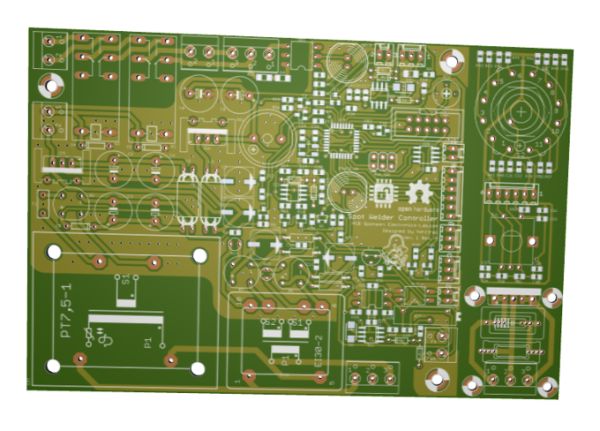
The author built a dual-pulse spot welder controller using an Atmega328P due to capacitor cost constraints. The device features zero-cross detection, triac control for the transformer, an HD44780 display, SPI thermocouple interface, current peak detection, isolated foot switch, voltage monitoring, and user input via rotary switches. The power supply utilizes multiple transformers, rectifiers, regulators, and filtering components. This design is also adaptable for AC dimmers or thermostats.
Parts used in the MCU Controlled Spot Welder:
- Atmega328P microcontroller
- HD44780 LCD interface
- SPI interface for single thermocouple
- Current transformer with peak detector
- Isolated foot switch
- Opamps for voltage monitoring
- Single rotary switch for operation
- Single rotary encoder for settings
- 1x12VAC 1Amp main transformer (TR-15)
- 2x9Vac 0.1Amp secondary transformer
- 0.9A PTC fuse
- 2W10 bridge rectifier
- 1n4007 diode
- Smoothing capacitors
- Common mode choke
- 7812 linear voltage regulator with heatsink
- 7805 linear voltage regulator
- 2n3904 npn transistor
- Triac for transformer control
Description
I always wanted a spot welder, so I decided to built one. I wanted to build a capacitance discharge one but I couldnt afford for the capacitors at this time. So this is a controller for a dual pulse spot welder with some few extras:
– It has a zero cross detector. You could power the transformer at zero cross or dim the transformer if you like
– The transformer is triac controlled
– It has an hd44780 interface
– An spi interface for single thermocouple
– Peak detector of a current transformer
– Isolated foot switch
– Voltage monitor with opmaps
– An attempt to sense when the user tries to weld
– Single rotary switch for operation and single rotary encoder for setting up
I have used an Atmega328P and I will probably write the code in arduino IDE.
You could probably use the pcb for other applications, like:
– Ac dimmer
– Simple thermostat, or
– PID thermostat with dimming output
Further update on the project after the delivery on the pcbs
Schematics
Power Supply
The main power supply for the controller. The main transformer is 1x12VAC 1Amp (TR-15)
The PTC fuse is 0.9A with a 2W10 bridge rectifier and a 1n4007 diode, smoothing capacitors, common mode choke to remove any spikes and unwanted noise, some more capacitors, linear voltage regulator 7812 with heatsink, more caps, more chokes, more caps again, 7805 and 5v rail.
The T7 is a 2n3904 npn transistor that senses both of the AC zero crosses for the dimming circuit.
The other transformer is a 2x9Vac 0.1Amp for the secondary isolated circuits
For more detail: MCU Controlled Spot Welder
-
Why did the author build a capacitance discharge spot welder?
The author wanted to build one but could not afford the capacitors at that time. -
What microcontroller is used in this project?
An Atmega328P is used and the code will likely be written in Arduino IDE. -
How does the device detect AC zero crosses?
A T7 2n3904 npn transistor senses both of the AC zero crosses for the dimming circuit. -
What are the specifications of the main transformer?
The main transformer is a 1x12VAC 1Amp unit labeled TR-15. -
Can this PCB be used for other applications?
Yes, it can be used as an AC dimmer, a simple thermostat, or a PID thermostat with dimming output. -
What type of rectifier is used in the power supply?
A 2W10 bridge rectifier is used along with a 1n4007 diode. -
How is the transformer controlled in this design?
The transformer is controlled by a triac which allows for zero cross powering or dimming. -
What interface is used for the thermocouple?
An SPI interface is included for connecting a single thermocouple.
