Summary of Low-tech and High-tech POV (Persistence of Vision)
Persistence of vision creates optical illusions where rapid sequential images merge into a single visible form. This article demonstrates two methods: a low-tech cardboard spinner and a high-tech LED wand controlled by an Arduino. The low-tech version uses printed lines on rotating cardboard, while the high-tech version employs flickering LEDs moved horizontally in the dark to display text like "hello."
Parts used in Persistence of Vision Project:
- Long shish-kabob stick or knitting needle
- Corrugated cardboard
- Paper for printing
- Labels
- Clear tape
- Computer (Apple iMac)
- Arduino Uno board
- USB cable
- Breadboard
- 7 LEDs of the same color
- 7 resistors 220 ohms
- 10k resistor
- Push-button switch
- Small piece of thin cardboard
- Paper clip
- Electrical tape or duct tape
Persistence of vision is an optical illusion. When we look at an object, our eyes keep seeing an image of it for a fraction of a second after the object is removed. If several images appear quickly after each other, they seem to merge.
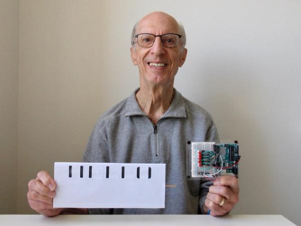
My low-tech example is a piece of cardboard with vertical lines on one side and horizontal lines on the other. When it spins, a word becomes visible.
The high-tech example has a small computer and a single row of LEDs that flicker in a specific order. When the LEDs are moved sideways quickly, letters appear and form a word. The result is best seen in the dark.
A very good video of other low-tech examples may be found onYouTube in “What is Persistence of Vision? (Mr. Wizard)” https://www.youtube.com/watch?v=YismwdgMIRc
Parts for the Low-tech Example
- Long shish-kabob stick or knitting needle or similar stick
- Corrugated cardboard
- Paper for printing
- Labels
- Clear tape
Parts for the High-tech Example
- A computer (I used an Apple iMac)
- Arduino Uno or another model and its USB cable
- Breadboard, preferably attached to the Arduino
- 7 LEDs of the same color
- 7 resistors 220 ohms
- 10k resistor
- Push-button switch
- Small piece of thin cardboard
- Paper clip
- Small piece of electrical tape or duct tape
Step 1: Make the Low-tech Example
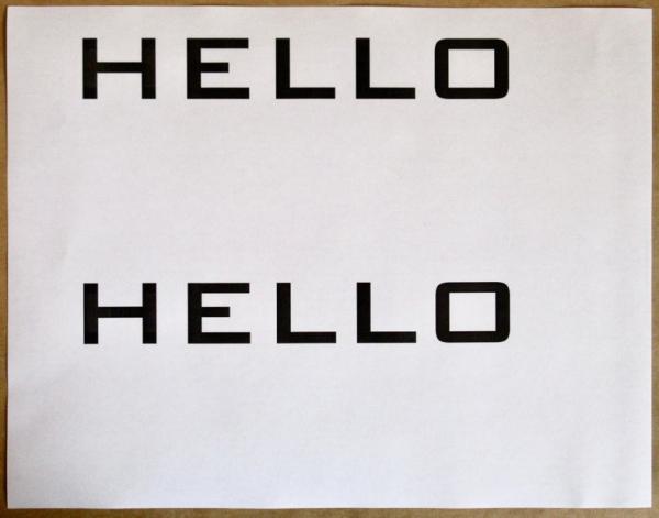
Choose a word and print two copies. The font for my HELLO sign is 144-point Bank Gothic.
Cut some labels and stick them on the copies of the word, such that one copy has only vertical lines and the other has only horizontal lines.
Decide on the size of the sign. The long dimension has to be shorter than the length of the shish-kabob stick. Cut the corrugated cardboard, with the corrugation holes running lengthwise, and making sure that one of the corrugation holes is in the exact middle. Cut the two paper copies to the same size, being careful that one copy will align on one side of the cardboard exactly with the other copy on the other side.
Attach the copies to the cardboard. I used labels and covered the long edges of the cardboard, so that the brown edges don’t show when the cardboard spins.
Push the shish-kabob stick down the exact middle hole of the cardboard, with both ends sticking out.
Spin the finished sign with your fingers, holding both ends of the shish-kabob stick.
You could also put one end of the stick in a power drill and spin it. This gives a very good result.
Step 2: Wire the Arduino
If you’re not familiar with the Arduino, the following links may be useful:
Getting started with Arduino: https://www.arduino.cc/en/Guide
https://www.instructables.com/A-Beginners-Guide-to-Arduino/
Online Arduino class: https://www.instructables.com/Arduino-Class/
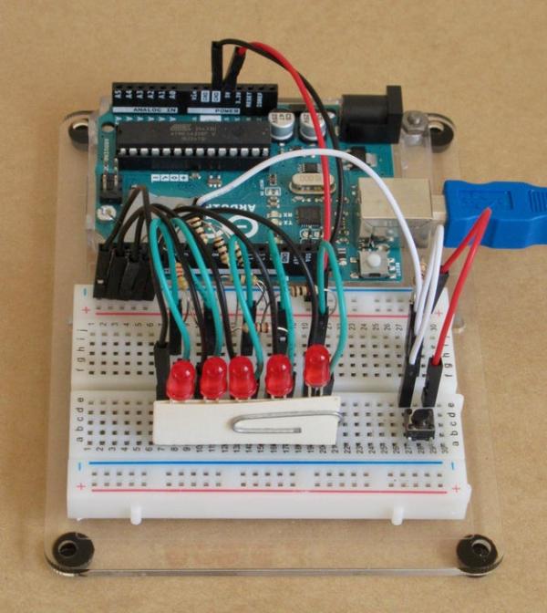
The circuit is shown in the photo and described below. I used several wires to make the connections.
- Arduino’s +5V goes to + on the breadboard
- Arduino’s GND goes to – on the breadboard
- The seven 220 ohm resistors go from pins 2 thru 6 of the Arduino to separate pins on the breadboard
- The long wires of the seven LEDs go to those pins on the breadboard, and the short wires go to – on the breadboard
- The 10K resistor goes from the Arduino’s pin 7 to – on the breadboard
- The push-button switch should be placed in an outside corner of the breadboard, so that it can be pressed easily. One side goes to the 10K resistor that goes to pin 7
- The other side of the switch goes to + on the breadboard
- Cut a small piece of cardboard (bent in the middle) to fit onto both sides of the LED wires, and attach with a paper clip. This will keep the LEDs from flopping around when moved back and forth quickly.
- Stick 2 pieces of electrical tape or duct tape, one on top of the other, over the green light of the Arduino.
Step 3: The Arduino Sketch (The Code)
The code was downloaded from a Hackster project titled “Arduino Horizontal POV Display” https://www.hackster.io/mircemk/arduino-horizontal-pov-display-dcf041 and then modified as follows:
- Increase delayTime & charBreak (at beginning), because my project is a wand-type but the Hackster project was a motorized spinning type, which moves the LEDs much faster.
- Add a push-button so that the LEDs will start flashing when the button is pressed.
- Renumber the LED pins.
- Change “hello world” (at end) to “hello”.
The Arduino sketch (the code) may be downloaded from the .ino file located in this step, or the following code could be copied and pasted into a new Arduino sketch.
// Simple POV display for a wand or horizontal, cylindrical display.
// Downloaded from a hackster.io project titled “Arduino Horizontal POV Display”
// and modified: added pushbutton, increased LED times, renumbered LED pins..
// – pushbutton attached to pin 7 from +5V
// – 10K resistor attached to pin 7 from ground
int delayTime = 10; // To watch how the LEDs form the letters, set this to 500
int charBreak = 20; // and set this one to 1000
int LED1 = 2;
int LED2 = 3;
int LED3 = 4;
int LED4 = 5;
int LED5 = 6;
const int buttonPin = 7;
int buttonState = 0;
void setup(){
pinMode(LED1, OUTPUT);
pinMode(LED2, OUTPUT);
pinMode(LED3, OUTPUT);
pinMode(LED4, OUTPUT);
pinMode(LED5, OUTPUT);
pinMode(buttonPin, INPUT);
}
// These statements define which LEDs are turned on for each of 5 time slices,
// for a letter. For example
// L is 31,1,1,1,0 which in binary is 11111,00001,00001,00001,00000
// H is 31,4,4,4,31 which in binary is 11111.00100,00100,00100,11111
int a[] = {1, 6, 26, 6, 1};
int b[] = {31, 21, 21, 10, 0};
int c2[] = {14, 17, 17, 10, 0};
int d[] = {31, 17, 17, 14, 0};
int e[] = {31, 21, 21, 17, 0};
int f[] = {31, 20, 20, 16, 0};
int g[] = {14, 17, 19, 10, 0};
int h[] = {31, 4, 4, 4, 31};
int i[] = {0, 17, 31, 17, 0};
int j[] = {0, 17, 30, 16, 0};
int k[] = {31, 4, 10, 17, 0};
int l[] = {31, 1, 1, 1, 0};
int m[] = {31, 12, 3, 12, 31};
int n[] = {31, 12, 3, 31, 0};
int o[] = {14, 17, 17, 14, 0};
int p[] = {31, 20, 20, 8, 0};
int q[] = {14, 17, 19, 14, 2};
int r[] = {31, 20, 22, 9, 0};
int s[] = {8, 21, 21, 2, 0};
int t[] = {16, 16, 31, 16, 16};
int u[] = {30, 1, 1, 30, 0};
int v[] = {24, 6, 1, 6, 24};
int w[] = {28, 3, 12, 3, 28};
int x[] = {17, 10, 4, 10, 17};
int y[] = {17, 10, 4, 8, 16};
int z[] = {19, 21, 21, 25, 0};
int eos[] = {0, 1, 0, 0, 0};
int excl[] = {0, 29, 0, 0, 0};
int ques[] = {8, 19, 20, 8, 0};
void displayLine(int line){
int myline;
myline = line;
if (myline>=16) {digitalWrite(LED1, HIGH); myline-=16;} else {digitalWrite(LED1, LOW);}
if (myline>=8) {digitalWrite(LED2, HIGH); myline-=8;} else {digitalWrite(LED2, LOW);}
if (myline>=4) {digitalWrite(LED3, HIGH); myline-=4;} else {digitalWrite(LED3, LOW);}
if (myline>=2) {digitalWrite(LED4, HIGH); myline-=2;} else {digitalWrite(LED4, LOW);}
if (myline>=1) {digitalWrite(LED5, HIGH); myline-=1;} else {digitalWrite(LED5, LOW);}
}
void displayChar(char c){
if (c == ‘a’){for (int i = 0; i <5; i++){displayLine(a[i]);delay(delayTime);}displayLine(0);}
if (c == ‘b’){for (int i = 0; i <5; i++){displayLine(b[i]);delay(delayTime);}displayLine(0);}
if (c == ‘c2’){for (int i = 0; i <5; i++){displayLine(c2[i]);delay(delayTime);}displayLine(0);}
if (c == ‘d’){for (int i = 0; i <5; i++){displayLine(d[i]);delay(delayTime);}displayLine(0);}
if (c == ‘e’){for (int i = 0; i <5; i++){displayLine(e[i]);delay(delayTime);}displayLine(0);}
if (c == ‘f’){for (int i = 0; i <5; i++){displayLine(f[i]);delay(delayTime);}displayLine(0);}
if (c == ‘g’){for (int i = 0; i <5; i++){displayLine(g[i]);delay(delayTime);}displayLine(0);}
if (c == ‘h’){for (int i = 0; i <5; i++){displayLine(h[i]);delay(delayTime);}displayLine(0);}
if (c == ‘i’){for (int it = 0; it <5; it++){displayLine(i[it]);delay(delayTime);}displayLine(0);}
if (c == ‘j’){for (int i = 0; i <5; i++){displayLine(j[i]);delay(delayTime);}displayLine(0);}
if (c == ‘k’){for (int i = 0; i <5; i++){displayLine(k[i]);delay(delayTime);}displayLine(0);}
if (c == ‘l’){for (int i = 0; i <5; i++){displayLine(l[i]);delay(delayTime);}displayLine(0);}
if (c == ‘m’){for (int i = 0; i <5; i++){displayLine(m[i]);delay(delayTime);}displayLine(0);}
if (c == ‘n’){for (int i = 0; i <5; i++){displayLine(n[i]);delay(delayTime);}displayLine(0);}
if (c == ‘o’){for (int i = 0; i <5; i++){displayLine(o[i]);delay(delayTime);}displayLine(0);}
if (c == ‘p’){for (int i = 0; i <5; i++){displayLine(p[i]);delay(delayTime);}displayLine(0);}
if (c == ‘q’){for (int i = 0; i <5; i++){displayLine(q[i]);delay(delayTime);}displayLine(0);}
if (c == ‘r’){for (int i = 0; i <5; i++){displayLine(r[i]);delay(delayTime);}displayLine(0);}
if (c == ‘s’){for (int i = 0; i <5; i++){displayLine(s[i]);delay(delayTime);}displayLine(0);}
if (c == ‘t’){for (int i = 0; i <5; i++){displayLine(t[i]);delay(delayTime);}displayLine(0);}
if (c == ‘u’){for (int i = 0; i <5; i++){displayLine(u[i]);delay(delayTime);}displayLine(0);}
if (c == ‘v’){for (int i = 0; i <5; i++){displayLine(v[i]);delay(delayTime);}displayLine(0);}
if (c == ‘w’){for (int i = 0; i <5; i++){displayLine(w[i]);delay(delayTime);}displayLine(0);}
if (c == ‘x’){for (int i = 0; i <5; i++){displayLine(x[i]);delay(delayTime);}displayLine(0);}
if (c == ‘y’){for (int i = 0; i <5; i++){displayLine(y[i]);delay(delayTime);}displayLine(0);}
if (c == ‘z’){for (int i = 0; i <5; i++){displayLine(z[i]);delay(delayTime);}displayLine(0);}
if (c == ‘!’){for (int i = 0; i <5; i++){displayLine(excl[i]);delay(delayTime);}displayLine(0);}
if (c == ‘?’){for (int i = 0; i <5; i++){displayLine(ques[i]);delay(delayTime);}displayLine(0);}
if (c == ‘.’){for (int i = 0; i <5; i++){displayLine(eos[i]);delay(delayTime);}displayLine(0);}
delay(charBreak);
}
void displayString(char* s){
for (int i = 0; i<=strlen(s); i++){
displayChar(s[i]);
}
}
void loop(){
// read the state of the pushbutton value:
buttonState = digitalRead(buttonPin);
// check if the pushbutton is pressed. If it is, the buttonState is HIGH:
if (buttonState == HIGH) {
displayString(“hello”);
}
}
The sketch should compile successfully, but there will probably be a couple of warning messages. They may be ignored.
If you would like to watch how the LEDs form the letters, set delayTime to 500 and charBreak to 1000, at the beginning of the sketch.
Step 4: Run the Example
A dark room shows the best result. You could have the Arduino either plugged in the computer using the USB cable, or connected to batteries or a wall-plug power supply of 5 or 6 volts.
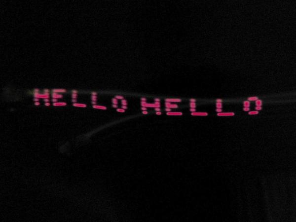
Holding the line of LEDs in a vertical position, start moving the Arduino/breadboard horizontally quite quickly, and push the pushbutton switch. The LEDs will start to flicker when you push the switch. Move the unit back and forth quickly. The letters should be visible.
The photo had a long exposure (very slow shutter speed) to capture all the LED flickering and thus show the words.
Source: Low-tech and High-tech POV (Persistence of Vision)
- What is persistence of vision?
It is an optical illusion where eyes keep seeing an image for a fraction of a second after the object is removed, causing quickly appearing images to merge. - How can I make a low-tech example?
Print a word twice, cut labels to create vertical lines on one copy and horizontal lines on the other, attach them to corrugated cardboard with a hole in the middle, insert a stick, and spin it. - Can I use a power drill for the low-tech example?
Yes, you can put one end of the stick in a power drill to spin it, which gives a very good result. - How do I wire the Arduino for the high-tech example?
Connect +5V and GND to the breadboard, place seven 220 ohm resistors from pins 2-6 to the breadboard, connect LEDs to those pins, and attach a push-button switch to pin 7 with a 10K resistor. - Where did the Arduino code come from?
The code was downloaded from a Hackster project titled Arduino Horizontal POV Display and modified to add a pushbutton and change the text. - What is the best way to see the high-tech example clearly?
The result is best seen in the dark, and moving the unit back and forth horizontally quite quickly makes the letters visible. - How do I adjust the code to watch how the LEDs form letters?
Set delayTime to 500 and charBreak to 1000 at the beginning of the sketch. - Does the Arduino need to be plugged into a computer?
No, the Arduino can be connected to batteries or a wall-plug power supply of 5 or 6 volts.