Summary of Halloween Animated Knights
The author hacked two discounted life-sized animated Halloween knights to create an interactive entrance display. Using Arduinos, pneumatics, and audio boards, the knights detect approaching visitors via PIR sensors, block their path with swinging swords, tell synchronized jokes, and then lift their swords to let trick-or-treaters pass. The system features a master controller in the garage that manages remote start commands, pneumatic solenoids, and sensor inputs, while individual knight controllers handle jaw movement, eye lighting, and audio playback.
Parts used in the Animated Halloween Knights:
- Sainsmart 8-Relay board
- Arduino Nano Every
- Solenoid Switch
- Solenoid Master Valve
- 1/4" pneumatic hose AR
- RS485 Module
- 5-pin header socket
- 5x7 proto board
- Toggle switch SPST
- Push button - momentary
- Resistor
- LED
- Fuse Holder
- Terminal Block (2-tab)
- Terminal Block (3-tab)
- 5 Header connector AR
- Particle Photon
- PIR sensor (HC-SR501)
- 6" black 2" PVC pipe
- 3-D Print PIR Cap
- 3-D Print PIR mount
- 3-D Print stand
- Hex bolt, washers and wing nut
- Connector for cable to master controller
- Arduino MEGA 2650
- Adafruit Audio FX Sound Board 16 MB
- Velleman audio amp VMA408
- KA2284 Audio Meter
- 2N3904 Transistor
- 270 ohm resistor
- Level converters
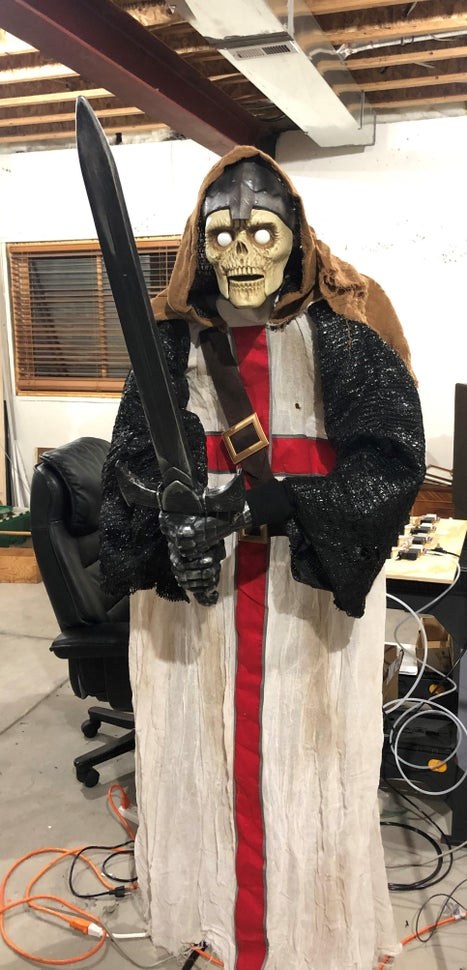
About a week or so after Halloween last year (pre-COVID), I happened to be in Home Depot and back in a far corner bin were several Halloween items very heavily discounted. They were just trying to get rid of them as fast as they could. There were two life-sized animated knights that I got for a steal. I decided to hack these to do more than just stand there with a moving jaw. I envisioned two knights that swing their swords to block the path to the house, talk to each other telling jokes and eventually raising their swords to let the Trick-or-Treaters pass. I can see Arduinos, pneumatics, WAV players…. Let the fun begin!
The Concept
I have several other animated Halloween props:
- A pneumatic scissor prop that is hidden behind some trees that flies out a life-sized spooky pumpkin-headed ghost with sound and lighted eyes about 8 feet and puts quite a scare on the kids.
- A Witch that is hidden in a window well that I fill with fog that pneumatically pops up, speaks with a moving jaw and glowing eyes.
- A large dragon that sits on top a balcony overlooking the entrance of the house. It makes noise, emits smoke and (simulated) fire from its jaws while rotating its head and flapping it’s wings.
- A Frankenstein monster that grunts, sways back and forth and waves it’s arms.
I already made a “remote master controller” that I keep in the garage that detects the people approaching by PIR sensors and drives the animations by controlling solenoids for the pneumatic cylinders in the props. I also keep my noisy compressor in the garage. So, it was easy to add another micro controller for the knight props and add another PIR sensor for this prop. I also have an enable switch so that if I wanted to disable the prop I can do this with a local toggle switch. The knights will stand on either side of the house entrance. A PIR sensor will detect when someone approaches, they swing their swords across the path, tells the kids to “HALT “and each knight tells them a joke in sync. Once the joke is complete, they lift their swords to allow them to pass. Each knight has a pneumatic piston to move the arms and swords, an internal micro controller to drive the audio files, drive the jaw movement and light up their eyes.
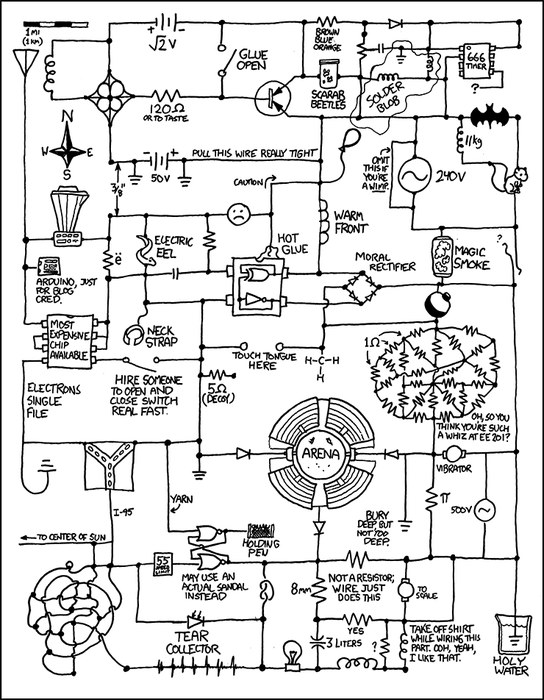
For this instructable, I will primarily focus on the knights. The schematic I’m showing is for all my animated props. I might work to add those in a later instructable.
This is my first version of this post and I’ll be doing some updates as I work the second knight and make some improvements!! Stay tuned.
Step 1: The First Prototype Video
This is only one of the knights. I fixed the audio so it says both sides of the joke but you get the idea. I will make up the second knight as a mirror image of this one. I still have some tweaking to do, fix the jaw movement, and adjust the arms so they cross over the walkway, but it’s close!
Step 2: Start of the Hack
Here is the original prop I bought at Home depot. I actually bought two. The video attached is what it did before I got to it. I then took the whole thing apart. I removed the capes and shoulder padding. I removed the electronics box, shoulder framing the head, arms all the way down to the metal frame.
I took the electronics box apart and took out the speaker. Now I have the start of my hack.
Step 3: Master Controller Parts
General Parts – Master Controller
- Sainsmart 8-Relay board (1)
- Arduino Nano Every (5)
- Solenoid Switch (4)
- Solenoid Master Valve (5)
- 1/4″ pneumatic hose AR
- Particle Photon (1)
RS485 Board
- RS485 Module (6)
- 5-pin header socket (2)
- 5×7 proto board (1)
Switch Board
- Toggle switch SPST (6)
- Push button – momentary (1)
- Resistor (5)
- Resistor (1)
- Resistor (1)
- LED (7)
Power Distribution Board
- Fuse Holder (12)
- Terminal Block (2-tab) (6)
- Terminal Block (3-tab) (6)
- 5 Header connector AR
Step 4: Master Controller – Knight Control
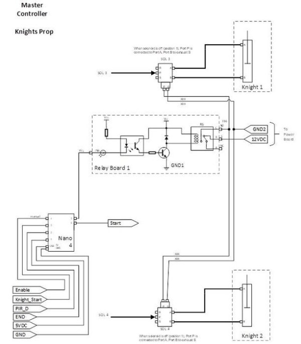
The master controller is remotely located in my garage and the knight props are located by the steps leading up to the front door. The master controller is based on an Arduino Nano Every. I picked this small micro controller for its size, plus for this use I didn’t need much in the way of I/O. The primary purpose of the Nano is to receive an external Passive Infrared (PIR) sensor signal when someone approaches. The code then tells the remote knights to start their animation cycle and also enables a pneumatic solenoid to drive the cylinders located in each knight for the mechanical arm animation. The master controller is based on an Arduino Nano Every. I picked this small microcontroller for its size, plus for this use I didn’t need much in the way of I/O. The primary purpose of the Nano is to receive an external Passive Infrared (PIR) sensor signal when someone approaches (I have a step later that describes this). The code then tells the remote knights to start their animation cycle and also enables a pneumatic solenoid to drive the cylinders located in each knight for the mechanical arm animation. I have an electrical cable from the Master Controller that supplies the control signals, electrical power to the knights and also pneumatic hoses to drive the pneumatic cylinders. I got some of that web mesh to cover it all.
The controller has four inputs. There is an Enable input, which is connected to a switch and used to enable or disable the prop locally. Another input is Knight Start. This is a signal from a Particle Proton. A Particle Proton is a Wi-Fi/web-based micro controller that allows me to control all of the animations from anywhere through my smart phone. I’ll discuss this a bit later. Another input is a Passive Infrared (PIR) sensor (PIR D). The PIR sensor detects when someone comes close to the knights. The last input is END. This is an input from the knights and signals when the knight is finished with telling the joke and its animations and is ready to swing the swords out of the way. Since each “joke” is of varying length, I decided to use an END signal instead of a generic delay. That way as soon as the joke is done, regardless of length, the swords swing open to let the kids pass.
The Nano is programmed to first check if the prop is enabled (the local switch), if not it returns to the start loop and will continue looping until I enable it. If enabled, it then checks to see if it is being remotely commanded to start (Knight Start). If so, it initiates the animation cycle, if not it continues and then checks to see if the PIR sensor (PIR D) detected someone. If not, it returns to the loop and continues until something happens. I’ll go through this in the code walk-through. The Nano has two outputs, one triggers a relay to enable two solenoids connected to a compressor. Each solenoid is connected to its respective knight and drives a pneumatic cylinder that rotates the knight’s swords to block the path. The other output is a signal that is transmitted to each knight to tell its internal micro controller to start its animation cycle.
I have lots of schematics, might be hard to go back and forth – but don’t worry, I have the entire set later on for download, so bear with me.
Step 5: Communicating With the Knights
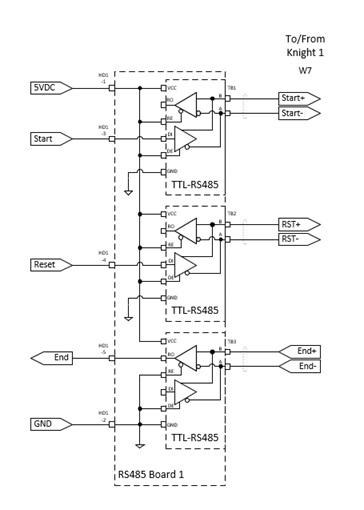
Because of the distance, I used an RS-485 transceiver to drive these signals from the Master Controller in the garage to each knight and is also used for the other input from the knights (END). I should also mention that along with the digital communications, I include remote 5VDC power to each knight through the cable. That way there is only one cable to each knight that I can hide (and also prevent little feet from tripping).
Step 6: Enable Switches and Reset
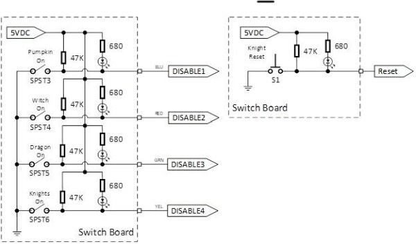
These are the enable switches used to enable and disable each prop. There is also a reset push-button which will reset each knight’s microcontroller in case they get out of sync with each other. I’ll explain this later in the code walk-through.
Step 7: Power Distribution
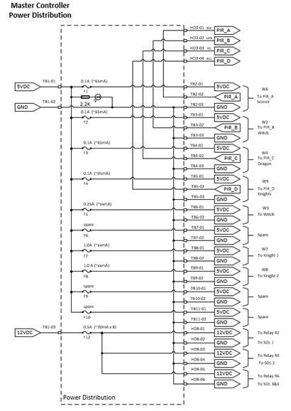
I have a pretty extensive power distribution with a 10A, 5VDC supply and also include fuses in case I have a short in one of the remote sensors or props.
You can see I show the Photon which receives remote command through the BLYNK app on my iPhone and Tablet. This allows me to manually start the props. This is WAY simple so I did not have to attempt any iPhone coding or GUI – this app has it all and has a simple GUI. I might also say it’s free, for small projects and private use.
I had a few issues with communicating from the Photon to the Arduinos since the Photon has 3.3 V logic and the Arduino is 5 V logic. I added an inexpensive 3.3 to 5 VDC level converters to the Arduino (easier than fussing with pull-ups).
Step 8: PIR Sensor
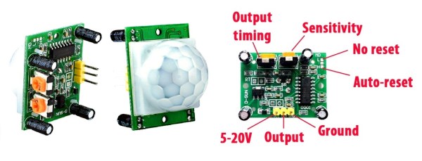
I use a simple PIR sensor (HC-SR501). This is a very cheap sensor that is widely used. Lots of on-line information on how to use this and how to use with an Arduino. The field of view is very wide. One could adjust the sensitivities but I needed something that would have a very narrow field of view so that it would only trigger when someone passes directly in path of it. You can experiment with the sensitivity so that it works as you like. The output timing is how long the output pulse lasts. I kept it pretty short, long enough for my micro controller and code loop to detect an event. It is a pretty long length of wire, but it seems to work OK.
So I came up with a sensor assembly that I can mass produce and use for all my Halloween props.
Step 9: Sensor Parts
Sensor Assembly:
- PIR sensor (HC-SR501)
- 6″ black 2″ PVC pipe
- 3-D Print PIR Cap
- 3-D Print PIR mount
- 3-D Print stand (legs, wedge, clamp)
- Hex bolt, washers and wing nut
- Connector for cable to mater controller (AR)
Step 10: PIR Sensor Assembly
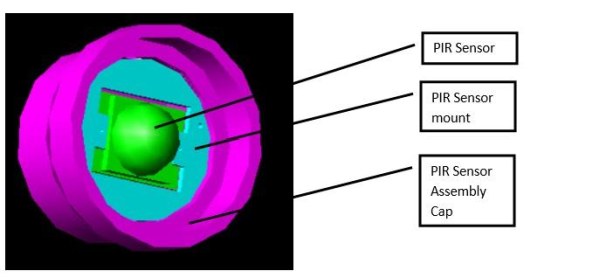
The assembled cap is placed on the end of a 6” length of 2” black PVC pipe so that the PIR has a very narrow field of view. The end of the cap also has a hole in the back for the +5VDC, GND and PIR Detect cable. I made up my own connector where one end plugs into the PIR 3-pin header and the other end is a JST-SM type 3-pin connector (no reason, I just had a few of those hanging around).
Step 11: Finished Sensor
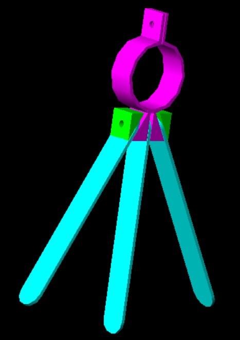
I also 3D printed a clamp and legs so I can set the sensor in the best location. I used wing nuts to quickly adjust the legs and clamp as needed.
The sensor is positioned in such a way that when the trick or treaters approach it kicks off the animations just at the right time automatically. The PIR Sensor is connected through a long-shielded cable to the master controller, which I hide in my garage along with my air compressor.
Step 12: Knights
The next steps describe what is installed inside the knights. The Halloween Knight Prop is based on an Arduino MEGA 2650. The Arduino MEGA 2650 is a larger microcontroller that has many I/O pins. The knight controller is substantially more complex and has many additional inputs/outputs. Out of all my props, this one is the most challenging.
The Arduino is programmed to make the Knight speak and move its jaw. I used an Adafruit Audio FX Sound Board 16 MB. This card can hold 8 WAV files. Each wave file is only one side of the joke. One half of the conversation is stored in the sound board. An identical board is in the other knight. The audio track is initiated in both knights at the same time, but timed so that it appears they are having a conversation. (More on this later)
The (R) output of the FX board is connected to a Velleman audio amp VMA408 and then to a speaker. I didn’t see the need for stereo.
Step 13: Knight Parts
Knight Controller Parts
- Arduino MEGA
- Adafruit Audio FX Sound Board 16 MB
- Velleman audio amp VMA408
- KA2284 Audio Meter
- 2N3904 Transistor (2)
- 270 ohm resistor (2)
Step 14: Driving the Jaw Based on the WAV File
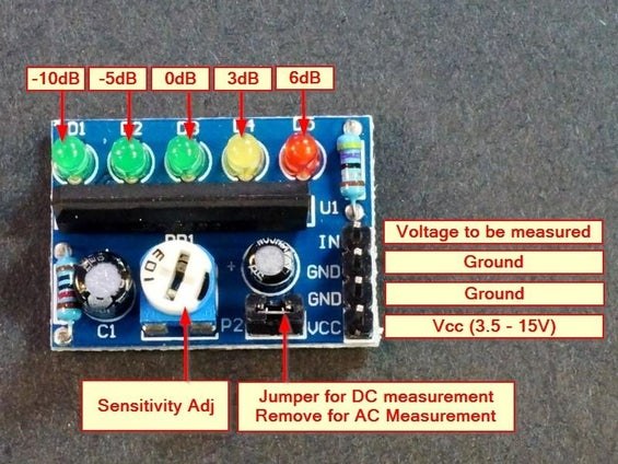
The other discrete channel output of the Adafruit Sound Board (L) is connected to an KA2284 Audio Meter. I soldered wire to each of the KA2284 LED high-side pins of D2, D3 and D4 and connected to A0, A1 and A2 of the Arduino.
The knight skull jaw is driven by a motor and a spring to return it to closed. Jaw control requires more current than the Arduino digital out, so I used a 2N3904 transistor as a driver. Use 270 ohm base resistor, connect emitter to ground and the Jaw between a separate 5 VDC supply and the collector.
Step 15: Knight Eyes
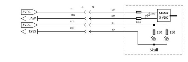
I could probably drive the skull eye LED’s directly from the Arduino but I had room and replicated the drive circuit for the Eyes as well. The Skull LEDs for the eyes are driven by a 2N3904 transistor as a driver for the Arduino Digital pin 49. I used a 270 ohm base resistor, Connect emitter to ground and the LED between a the 5 VDC supply and the collector.
I placed a 150 ohm resistor in serial with the LED’s since I’m driving with my 5 VDC supply. OK, I’ll admit, I thought the original circuit had resistors in line (there was a bunch of tape and goop over them), but I burned out the LED’s and had to replace them. Dang – out 5 cents. For my second knight, I’ll add resistors in serial – maybe that will give them different looking eyes?
Source: Halloween Animated Knights
- How does the system detect when someone approaches?
A Passive Infrared (PIR) sensor detects when a person comes close to the knights and triggers the animation cycle. - Can I control the props remotely from my phone?
Yes, a Particle Photon receives commands through the BLYNK app on an iPhone or Tablet to manually start the animations. - What allows the knights to swing their swords?
Pneumatic cylinders driven by solenoids connected to a compressor rotate the knight's swords to block or clear the path. - How do the knights synchronize their joke conversation?
Identical Adafruit Audio FX Sound Boards in each knight play WAV files timed so they appear to be having a conversation. - What component drives the movement of the knight's jaw?
An KA2284 Audio Meter reads the audio signal to drive a motor and spring mechanism that moves the jaw. - How are the knight's eyes lit up?
The skull LEDs for the eyes are driven by a 2N3904 transistor controlled by an Arduino digital pin. - Why is an RS-485 transceiver used in this project?
It is used to drive signals over the long distance between the master controller in the garage and the knights at the front door. - What happens if the knights get out of sync?
A reset push-button can be pressed to reset each knight's microcontroller and resynchronize them. - How is power distributed to the remote sensors and props?
A 10A, 5VDC supply with fuses is used to protect against shorts in the remote sensors or props. - What type of microcontroller is used inside the knight prop itself?
An Arduino MEGA 2650 is used because it has many I/O pins required for the complex inputs and outputs of the knight.