Story
Throughout my years of experience, I’ve created numerous timers and encountered a plethora of mobile apps. However, when I found myself in need of a straightforward solution to seamlessly automate the on-off cycle of a circuit I was actively developing, none of the available options proved to be the right fit. Consequently, I took it upon myself to construct what is now known as this relay timer.
Demonstration
Operation
Control over the timer is achieved through a set of five buttons.
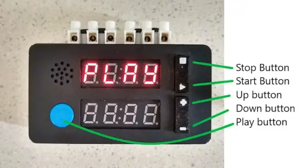
Within the Menu mode, when the timer is not in operation, the Stop and Start buttons facilitate navigation through the subsequent adjustable parameters.
- OFF Format – Shown as “OF F” – Determines whether the displayed OFF time is presented in hours and minutes or in minutes and seconds. Toggle between two choices, “HHnn” or “nnSS,” using the Up/Down buttons
- OFF Time (left two digits flashing) – Displayed as “OF t” – Represents the OFF time in hours or minutes based on the selected OFF format. Adjust the left two digits using the Up/Down buttons.
- OFF Time (right two digits flashing) – Displayed as “OF t” – Represents the OFF time in minutes or seconds based on the chosen OFF format. Set the right two digits using the Up/Down buttons.
- On format – Indicated as “ON F” – Determines whether the displayed ON time is presented in hours and minutes or in minutes and seconds. Toggle between two options, “HHnn” or “nnSS,” using the Up/Down buttons.
- On time (left two digits flashing) – Displayed as “ON t” – Represents the ON time in hours or minutes based on the selected ON format. Adjust the left two digits using the Up/Down buttons.
- On time (right two digits flashing) – Displayed as “ON t” – Represents the ON time in minutes or seconds based on the chosen ON format. Set the right two digits using the Up/Down buttons.
Loop – Shown as “LOOP” – Determines whether the sequence, once started, plays once or is repeated continuously. Switch between two options, “ON” or “OFF,” using the Up/Down buttons.
When in Menu mode and the display indicates “PLAY,” activating the Play button initiates the timer. If no OFF time or ON time is configured, the lower line will display “Err” and revert to Menu mode. Upon setting the OFF time, ON time, or both, the timer will commence. The buttons fulfill the following roles:
- Stop button – Temporarily halts the countdown.
- Start button – Resumes the countdown from a paused state.
- Play button – Interrupts the countdown, reverting to Menu mode when paused. Additionally, the relay will deactivate.
In the absence of looping, once the sequence concludes, the system will automatically transition into pause mode, displaying “dONE” on the upper screen. Simultaneously, the relay will deactivate.
3D printing
The necessary STL files for 3D printing are provided. You can choose to either 3D print them on your own if you have access to a 3D printer, or you can opt to have them printed at a commercial 3D printing service.
The suggested Slicer configuration is outlined below:
“Case – Bottom.stl” – 0.2 layer height, no supports
“Case – Front.stl” – 0.2 layer height, no supports
“Button_Tops.stl” – 0.1 layer height, no supports, switch to contrasting color at start of layer 54
“Spacers.stl” – 0.1 layer height, no supports
Enlarge the holes for the four PCB mounts using a 2.5mm drill bit and then thread them using a 3mm tap.
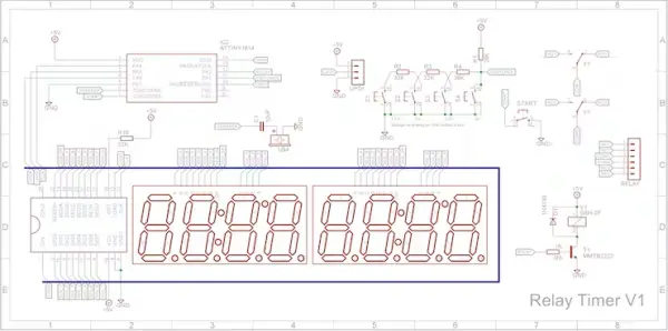
Schematic
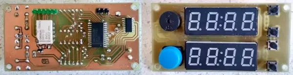
The timer employs an ATtiny1614 microprocessor in conjunction with a MAX7219 8-digit LED driver IC. The Start/Stop/Up/Down buttons are linked to a voltage divider, allowing them to share a solitary analog pin on the microprocessor. The DPDT relay, an Omron G6H-2F, was obtained from a Rocky Electronics sale. The displays are 0.4-inch 4-Digit 7-Segment Clock displays procured from Ali Express.
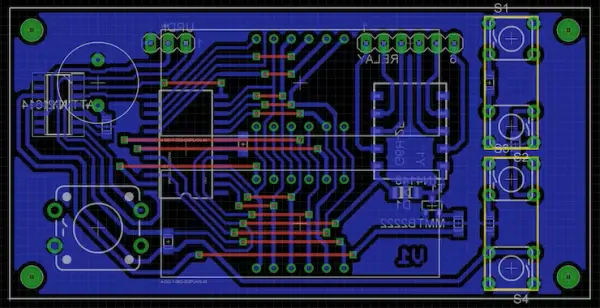
PCB
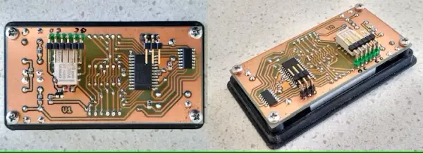
The PCB layout was tailored to accommodate components readily available in my workshop. The board incorporates a blend of through-hole components and Surface Mount Devices (SMD).
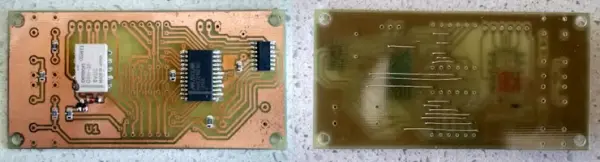
The Eagle files have been included for those interested in having the board professionally manufactured, or you can choose to follow my approach and create it independently. I utilized the Toner method for my own fabrication.
Assembly – Step 1
Commence by incorporating the Surface Mount Devices (SMD) components. Personally, I prefer utilizing solder paste over solder from a reel when soldering SMD components, finding it to be more convenient. For the reflow process beneath the SMD components, I employed my SMD Reflow Hot Plate.
If your board is single-sided, remember to include the required links.
Assembly – Step 2
Integrate a 3-pin straight male header onto the copper side of the board. This header serves the dual purpose of programming the ATtiny1614 and serving as the power connector. To prevent inadvertent errors, apply a touch of red paint to the +5V pin, ensuring the battery connector is not inserted incorrectly.
Incorporate a straight 6-pin male header onto the copper side of the board. This is where the wires connecting to the terminal blocks will be connected.
On the component side, attach the two 7-segment displays, four 6x6mm tactile switches with 8mm shafts, a 12x12mm tactile switch with a round button top, and the passive buzzer.
When affixing the 7-segment displays, be sure to include the 3D printed spacers underneath them. This ensures they are positioned at the correct height before soldering them into place.
Assembly – Step 3
Insert the Stop/Start and Up/Down button tops into their designated apertures, then secure the PCB to the front of the enclosure utilizing four 6mm M3 screws. Confirm the functionality of the buttons. In case the switches are hindered from operating smoothly, you might need to disassemble the PCB and carefully file away any obstructions.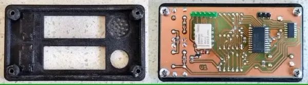
Assembly – Step 4
Attach right-angle male pin headers to the straight male pin headers that were affixed in Step 2; otherwise, the Dupont female connectors may not have sufficient clearance over the battery and charger board.
Assembly – Step 5
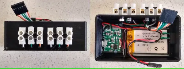
As per the MAX7219 datasheet, it requires a minimum supply voltage of 4.5V. Since this project utilizes a single 3.7V Li-Po battery, I incorporated a charger equipped with a boost circuit. These modules can be sourced from Ali-Express. Simply search for “USB 18650 Lithium Li-ion Battery Charger Module Boost 3.7V to 5V 9V 12V Adjustable DC-DC Step Up Boost Module.” These modules are usually priced around $1 each.
After connecting the battery wires and supply wires to the charger/boost module, securely affix the module to the base using hot glue.
To facilitate connections, two 3-way screw terminal connectors are affixed to the exterior of the case and linked to the relay outputs through wire holes. Be sure to drill suitable holes in the case to accommodate the terminal blocks you intend to use.
Programming
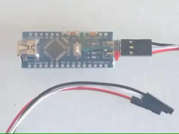
Differing from the previous ATtiny series like the ATtiny85, the ATtiny1614 utilizes the RESET pin for CPU programming. To program this microcontroller, an UPDI programmer is required. I constructed one by utilizing an Arduino Nano. Comprehensive construction guidelines can be accessed at “Create Your Own UPDI Programmer.” This resource also encompasses instructions for integrating the mega Tiny Core boards into your Integrated Development Environment (IDE).
After the board has been added to the IDE, choose it from the Tools menu.
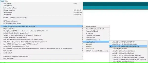
Choose the ATtiny1614 board in your IDE.
Select the appropriate settings for Board, chip, clock speed, COM port (the Arduino Nano is connected to), and the programmer.
Make sure to set the Programmer to jtag2updi (megaTinyCore).
Open the sketch and proceed to upload it to the ATtiny1614.
Code
/***************************************************************************
 * Relay Timer
 * by John Bradnam
 *
 * 2022-12-01 [email protected]
 *  - Created base code for ATtiny1614
 */

/**
 * ATTiny1614 Pins mapped to Ardunio Pins
 *
 *             +--------+
 *         VCC + 1   14 + GND
 * (SS)  0 PA4 + 2   13 + PA3 10 (SCK)
 *       1 PA5 + 3   12 + PA2 9  (MISO)
 * (DAC) 2 PA6 + 4   11 + PA1 8  (MOSI)
 *       3 PA7 + 5   10 + PA0 11 (UPDI)
 * (RXD) 4 PB3 + 6    9 + PB0 7  (SCL)
 * (TXD) 5 PB2 + 7    8 + PB1 6  (SDA)
 *             +--------+
 */

#ifdef __AVR_ATtiny1614__
#include <avr/eeprom.h>
#else
#include <EEPROM.h>
#endif

#include <LedControl.h>
#include "Display.h"
#include "Button.h"

#define MAX7219_DATA 2  //PA6
#define MAX7219_CLK 0   //PA4
#define MAX7219_LOAD 1  //PA5

#define SW_START 5      //PB2
#define SWITCHES 8      //PA1
#define RELAY 9         //PA2

#define SPEAKER 4       //PB3
#define BUZZER_PORT PORTB
#define BUZZER_PIN  PIN3_bm

//Button definitions
enum buttonEnum { BTN_NONE, BTN_STOP, BTN_START, BTN_DOWN, BTN_UP, BTN_BIG };

//void stopButtonPressed(void);
//void startButtonPressed(void);
void downButtonPressed(void);
void upButtonPressed(void);

Button* startButton;
Button* stopButton;
Button* downButton;
Button* upButton;
Button* bigButton;

//Menu definitions
enum menuEnum { TIMER, OFF_FMT, OFF_MSB, OFF_LSB, ON_FMT, ON_MSB, ON_LSB, LOOP };
enum formatEnum { HH_MM, MM_SS };
enum loopEnum { OFF, ON, DONE };

String menuText[] = { "", "OFF ", "OFF ", "ON  ", "ON  ", "LOOP" };
String formatText[] = { "hhnn", "nnss" };
String loopText[] = { "ON  ", "OFF " };

#define SETUP_FLASH_TIME 200
#define TIMER_FLASH_TIME 500
bool flashState = false;
bool flashTime = false;
bool flashColon = false;
unsigned long pauseDelay = 0;

bool inMenu = true;
menuEnum menuSelect = TIMER;
bool forceMenuUpdate = true;

//EEPROM handling
#define EEPROM_ADDRESS 0
#define EEPROM_MAGIC 0x0DAD0BAD
typedef struct {
  uint32_t magic;
  formatEnum offFormat;
  int offMsb;
  int offLsb;
  formatEnum onFormat;
  int onMsb;
  int onLsb;
  loopEnum timerLoop;
} EEPROM_DATA;

volatile EEPROM_DATA ee;       //Current EEPROM settings

volatile loopEnum timerState = OFF;
volatile int timerHours = 0;
volatile int timerMinutes = 0;
volatile int timerSeconds = 0;
volatile bool timerPaused = false;
volatile bool timerChanged = false;
volatile bool timerRelayChange = false;
bool relayIsOn = false;

//-------------------------------------------------------------------------
//Initialise Hardware

void setup()
{
  readEepromData();

  pinMode(SW_START, INPUT_PULLUP);
  pinMode(SWITCHES, INPUT);

  pinMode(RELAY, OUTPUT);
  digitalWrite(RELAY, LOW);
  relayIsOn = false;

  setupDisplay(MAX7219_DATA,MAX7219_CLK,MAX7219_LOAD);

  //Initialise buttons
  startButton = new Button(BTN_START, SWITCHES, 570, 669, false);
  startButton->Repeat(startButtonPressed);
  stopButton = new Button(BTN_STOP, SWITCHES, 670, 750, false);
  stopButton->Repeat(stopButtonPressed);
  downButton = new Button(BTN_DOWN, SWITCHES, 0, 100, false);
  downButton->Repeat(downButtonPressed);
  upButton = new Button(BTN_UP, SWITCHES, 460, 569, false);
  upButton->Repeat(upButtonPressed);
  bigButton = new Button(BTN_BIG, SW_START);

  // Initialize RTC
  while (RTC.STATUS > 0);                           // Wait until registers synchronized
  RTC.PER = 1023;                                   // Set period 1 second
  RTC.CLKSEL = RTC_CLKSEL_INT32K_gc;                // 32.768kHz Internal Oscillator
  RTC.INTCTRL = RTC_OVF_bm;                         // Enable overflow interrupt
  RTC.CTRLA = RTC_PRESCALER_DIV32_gc | RTC_RTCEN_bm;// Prescaler /32 and enable

  timerPaused = true;       //Stop timer
  timerChanged = true;      //Force repaint
  inMenu = true;            //Menu mode
  pauseDelay = millis() + SETUP_FLASH_TIME;         //Used to flash active setting

  //Enable interrupts
  sei();

}

//-------------------------------------------------------------------------
// Handle main loop

void loop()
{
  //No need to test buttons, callback routines will be invoked if pressed
  startButton->Pressed();
  stopButton->Pressed();
  upButton->Pressed();
  downButton->Pressed();

  if (inMenu)
  {
    if (millis() > pauseDelay)
    {
      flashColon = !flashColon;
      pauseDelay = millis() + SETUP_FLASH_TIME;
      forceMenuUpdate = true;
    }

    if (forceMenuUpdate)
    {
      displayMenu();
    }

    if (menuSelect == TIMER && bigButton->Pressed())
    {
      if (ee.offMsb != 0 || ee.offLsb != 0)
      {
        writeEepromData();
        timerState = OFF;
        timerChanged = true;
        if (ee.offFormat == HH_MM)
        {
          timerSeconds = 0;
          timerMinutes = ee.offLsb;
          timerHours = ee.offMsb;
        }
        else
        {
          timerSeconds = ee.offLsb;
          timerMinutes = ee.offMsb;
          timerHours = 0;
        }
        inMenu = false;
        timerPaused = false;
        timerRelayChange = true;
      }
      else if (ee.onMsb != 0 || ee.onLsb != 0)
      {
        writeEepromData();
        timerState = ON;
        timerChanged = true;
        if (ee.onFormat == HH_MM)
        {
          timerSeconds = 0;
          timerMinutes = ee.onLsb;
          timerHours = ee.onMsb;
        }
        else
        {
          timerSeconds = ee.onLsb;
          timerMinutes = ee.onMsb;
          timerHours = 0;
        }
        inMenu = false;
        timerPaused = false;
        timerRelayChange = true;
      }
      else
      {
        displayString("Err ", false, true);
      }
    }
  }
  else
  {
    //Handle coundown
    processTimer();

    if ((timerPaused || timerState == DONE) && bigButton->Pressed())
    {
      timerPaused = true;       //Stop timer
      timerChanged = true;      //Force repaint
      inMenu = true;            //Menu mode
      timerRelayChange = true;  //Force relay change
      pauseDelay = millis() + SETUP_FLASH_TIME;         //Used to flash active setting
    }
  }

  if (timerRelayChange)
  {
    bool on = (!inMenu && (timerState == ON));
    if (relayIsOn != on)
    {
      digitalWrite(RELAY, (on) ? HIGH : LOW);
      relayIsOn = on;
      beepRelay();
    }
    timerRelayChange = false;
  }

  delay(100);
}

//-------------------------------------------------------------------------
// In timer mode

void processTimer()
{
  if (timerChanged || millis() > pauseDelay)
  {
    if (timerPaused)
    {
      flashState = !flashState;
      flashTime = !flashTime;
    }
    else
    {
      flashState = true;
      flashTime = true;
    }
    flashColon = !flashColon;
    pauseDelay = millis() + TIMER_FLASH_TIME;

    displayString((timerState == OFF) ? "OFF " : (timerState == ON) ? "ON  " : "dONE", true, flashState);
    if ((timerState == OFF && ee.offFormat == HH_MM) || (timerState == ON && ee.onFormat == HH_MM))
    {
      displayDigits(timerHours, false, true, false, flashColon, flashTime);
      displayDigits(timerMinutes, false, false, true, false, flashTime);
    }
    else
    {
      displayDigits(timerMinutes, false, true, false, flashColon, flashTime);
      displayDigits(timerSeconds, false, false, true, false, flashTime);
    }
    timerChanged = false;
  }
}

//---------------------------------------------------------------
// Countdown the timer.
// This is invoked by RTC ISR every second
void countDownTimer()
{
  bool testAgain;
  if ((timerState == OFF && ee.offFormat == HH_MM) || (timerState == ON && ee.onFormat == HH_MM))
  {
    //HH-MM format
    if (timerSeconds > 0)
    {
      timerSeconds--;
    }
    else if (timerMinutes > 0)
    {
      timerSeconds = 59;
      timerMinutes--;
      timerChanged = true;
    }
    else if (timerHours > 0)
    {
      timerSeconds = 59;
      timerMinutes = 59;
      timerHours--;
      timerChanged = true;
    }
    testAgain = true;
    while (testAgain)
    {
      testAgain = false;
      if (timerSeconds == 0 && timerMinutes == 0 && timerHours == 0)
      {
        if (timerState == OFF)
        {
          timerState = ON;
          timerSeconds = 0;
          timerMinutes = ee.onLsb;
          timerHours = ee.onMsb;
          timerChanged = true;
          timerRelayChange = true;
          testAgain = true;
        }
        else if (ee.timerLoop == ON)
        {
          timerState = OFF;
          timerSeconds = 0;
          timerMinutes = ee.offLsb;
          timerHours = ee.offMsb;
          timerChanged = true;
          timerRelayChange = true;
          testAgain = true;
        }
        else
        {
          timerState = DONE;
          timerRelayChange = true;
          stopButtonPressed();
        }
      }
    }
  }
  else
  {
    //MM-SS format
    if (timerSeconds > 0)
    {
      timerSeconds--;
      timerChanged = true;
    }
    else if (timerMinutes > 0)
    {
      timerSeconds = 59;
      timerMinutes--;
      timerChanged = true;
    }
    testAgain = true;
    while (testAgain)
    {
      testAgain = false;
      if (timerSeconds == 0 && timerMinutes == 0 && timerHours == 0)
      {
        if (timerState == OFF)
        {
          timerState = ON;
          timerSeconds = ee.onLsb;
          timerMinutes = ee.onMsb;
          timerHours = 0;
          timerChanged = true;
          timerRelayChange = true;
          testAgain = true;
        }
        else if (ee.timerLoop == ON)
        {
          timerState = OFF;
          timerSeconds = ee.offLsb;
          timerMinutes = ee.offMsb;
          timerHours = 0;
          timerChanged = true;
          timerRelayChange = true;
          testAgain = true;
        }
        else
        {
          timerState = DONE;
          timerRelayChange = true;
          stopButtonPressed();
        }
      }
    }
  }
}

//---------------------------------------------------------------
// RTC Interrupt Handler
ISR(RTC_CNT_vect)
{
  if (!timerPaused)
  {
    countDownTimer();
  }
  RTC.INTFLAGS = RTC_OVF_bm;                         // Reset overflow interrupt
}

//-------------------------------------------------------------------------
// Callback for when START button is pressed

void startButtonPressed()
{
  if (inMenu)
  {
    beepDigit();
    menuSelect = (menuSelect == LOOP) ? TIMER : (menuEnum)((int)menuSelect + 1);
    forceMenuUpdate = true;
  }
  else if (timerPaused && timerState != DONE)
  {
    timerChanged = true;
    timerPaused = false;
  }
}

//-------------------------------------------------------------------------
// Callback for when STOP button is pressed

void stopButtonPressed()
{
  if (inMenu)
  {
    beepDigit();
    menuSelect = (menuSelect == TIMER) ? LOOP : (menuEnum)((int)menuSelect - 1);
    forceMenuUpdate = true;
  }
  else if (!timerPaused)
  {
    timerChanged = true;
    timerPaused = true;
    flashState = true;
    flashTime = true;
    flashColon = true;
  }
}

//-------------------------------------------------------------------------
// Callback for when + button is pressed

void upButtonPressed()
{
  if (inMenu)
  {
    forceMenuUpdate = true;
    switch (menuSelect)
    {
      case OFF_FMT: ee.offFormat = (ee.offFormat == HH_MM) ? MM_SS : HH_MM; break;
      case OFF_MSB: ee.offMsb = min(ee.offMsb + 1, 99); break;
      case OFF_LSB: ee.offLsb = min(ee.offLsb + 1, 59); break;
      case ON_FMT:  ee.onFormat = (ee.onFormat == HH_MM) ? MM_SS : HH_MM; break;
      case ON_MSB:  ee.onMsb = min(ee.onMsb + 1, 99); break;
      case ON_LSB:  ee.onLsb = min(ee.onLsb + 1, 59); break;
      case LOOP:    ee.timerLoop = (ee.timerLoop == ON) ? OFF : ON; break;
      default: forceMenuUpdate = false; break;
    }
    if (forceMenuUpdate)
    {
      beepDigit();
      flashColon = true;
      displayMenu();
    }
  }
}

//-------------------------------------------------------------------------
// Callback for when - button is pressed

void downButtonPressed()
{
  if (inMenu)
  {
    forceMenuUpdate = true;
    switch (menuSelect)
    {
      case OFF_FMT: ee.offFormat = (ee.offFormat == HH_MM) ? MM_SS : HH_MM; break;
      case OFF_MSB: ee.offMsb = max(ee.offMsb - 1, 0); break;
      case OFF_LSB: ee.offLsb = max(ee.offLsb - 1, 0); break;
      case ON_FMT:  ee.onFormat = (ee.onFormat == HH_MM) ? MM_SS : HH_MM; break;
      case ON_MSB:  ee.onMsb = max(ee.onMsb - 1, 0); break;
      case ON_LSB:  ee.onLsb = max(ee.onLsb - 1, 0); break;
      case LOOP:    ee.timerLoop = (ee.timerLoop == ON) ? OFF : ON; break;
      default: forceMenuUpdate = false; break;
    }
    if (forceMenuUpdate)
    {
      beepDigit();
      flashColon = true;
      displayMenu();
    }
  }
}

//-------------------------------------------------------------------------
// Display the current menu

void displayMenu()
{
  switch (menuSelect)
  {
    case TIMER: displayString("PLAY", true, true); displayString("   ", false, true); break;
    case OFF_FMT: displayFormat("OF F", ee.offFormat); break;
    case OFF_MSB: displayTime("OF t", ee.offMsb, ee.offLsb, ee.offFormat, true); break;
    case OFF_LSB: displayTime("OF t", ee.offLsb, ee.offMsb, ee.offFormat, false); break;
    case ON_FMT:  displayFormat("ON F", ee.onFormat); break;
    case ON_MSB: displayTime("ON t", ee.onMsb, ee.onLsb, ee.onFormat, true); break;
    case ON_LSB: displayTime("ON t", ee.onLsb, ee.onMsb, ee.onFormat, false); break;
    case LOOP: displayLoop(ee.timerLoop); break;
  }
  forceMenuUpdate = false;
}

//-------------------------------------------------------------------------
// Display the time format
//  s - String to display on top line
//  fmt - Format
void displayFormat(String s, formatEnum fmt)
{
  displayString(s, true, true);
  displayString((fmt == HH_MM) ? "hhnn" : "nnSS", false, flashColon);
}

//-------------------------------------------------------------------------
// Display the time format
//  s - String to display on top line
//  dyn - Dynamic variable to set
//  sta - Static variable to show
//  fmt - Format
//  left - true if adjusting left digit
void displayTime(String s, int dyn, int sta, formatEnum fmt, bool left)
{
  displayString(s, true, true);
  if (left)
  {
    displayDigits(dyn, false, true, true, flashColon, flashColon);
    displayDigits(sta, false, false, true, false, true);
  }
  else
  {
    displayDigits(sta, false, true, true, flashColon, true);
    displayDigits(dyn, false, false, true, false, flashColon);
  }
}

//-------------------------------------------------------------------------
// Display the time format
void displayLoop(loopEnum fmt)
{
  displayString("LOOP", true, true);
  displayString((fmt == ON) ? "ON  " : "OFF ", false, flashColon);
}

//---------------------------------------------------------------
//Write the EepromData structure to EEPROM
void writeEepromData()
{
  //This function uses EEPROM.update() to perform the write, so does not rewrites the value if it didn't change.
  #ifdef __AVR_ATtiny1614__
    eeprom_update_block (( void *) &ee , ( void *) EEPROM_ADDRESS, sizeof(ee));
  #else
    EEPROM.put(EEPROM_ADDRESS,ee);
  #endif
}

//---------------------------------------------------------------
//Read the EepromData structure from EEPROM, initialise if necessary
void readEepromData()
{
  //Eprom
  #ifdef __AVR_ATtiny1614__
    eeprom_read_block (( void *) &ee , ( const void *) EEPROM_ADDRESS, sizeof(ee));
  #else
    EEPROM.get(EEPROM_ADDRESS,ee);
  #endif
  #ifndef RESET_EEPROM
  if (ee.magic != EEPROM_MAGIC)
  #endif
  {
    ee.magic = EEPROM_MAGIC;
    ee.offFormat = MM_SS;
    ee.offMsb = 0;
    ee.offLsb = 0;
    ee.onFormat = MM_SS;
    ee.onMsb = 0;
    ee.onLsb = 0;
    ee.timerLoop = OFF;
    writeEepromData();
  }
}

//-----------------------------------------------------------------------------------
//Turn on and off buzzer quickly
void beepDigit()
{
  //PB3
#define BUZZER_PORT PORTB
#define BUZZER_PIN  PIN3_bm

  BUZZER_PORT.OUTSET = BUZZER_PIN;   // turn on buzzer
  delay(5);
  BUZZER_PORT.OUTCLR = BUZZER_PIN;  // turn off the buzzer
}

//-----------------------------------------------------------------------------------
//Turn on and off buzzer quickly
void beepRelay()
{
  BUZZER_PORT.OUTSET = BUZZER_PIN;   // turn on buzzer
  delay(20);
  BUZZER_PORT.OUTCLR = BUZZER_PIN;  // turn off the buzzer
}