Summary of Exploring Arduino: An Open-Source Platform for Creative Electronics Prototyping
Arduino is an open-source electronics platform for creating interactive projects using easy-to-use hardware and software. The article explains Arduino UNO and Mega2560 features, pin functions (digital, analog, PWM), power options, safety tips, IDE setup, uploading sketches (Blink example), LEDs and PWM control, transistor switching for high-current loads, LED strips (addressable and non-addressable), libraries (NeoPixel, FastLED), motors, tools, and basics of serial communication, memory, and interrupts for practical prototyping and engineering exercises.
Parts used in the Arduino Starter Kit / LED Exercises:
- Arduino UNO board
- Arduino Mega 2560 (mentioned)
- USB cable
- Breadboard
- 5mm LEDs (red, white, green, blue)
- 330Ω resistor
- 165Ω resistor (via parallel resistors)
- 22-Gauge solid wires
- Transistors: NPN BJT (e.g., P2N2222AG), TIP120/121/122
- N-channel MOSFETs (e.g., IRLB8721PbF, IRF630, IRF520)
- Power supply (5V or 12V DC bench supply or battery)
- LED strips (5050 RGB, WS2811, WS2812/WS2812B)
- DC motors (toy DC motors)
- Soldering station and accessories (solder, wick, stand)
- Digital multimeter
- Oscilloscope (optional)
- Function generator (optional)
- Masking tape or protective enclosure
- Screwdrivers, wire cutter, wire stripper, pliers
Introduction
Arduino represents an open-source electronics prototyping platform built upon versatile and user-friendly hardware and software components. Its purpose is to cater to artists, designers, hobbyists, and individuals keen on crafting interactive objects or environments.
Getting Started with Arduino UNO
The Arduino platform offers a variety of board options to choose from. For beginners, you can acquire a basic “Arduino UNO” board for under $5 through numerous online retailers. I recommend considering an “Arduino Starter Kit,” which includes an Arduino UNO board along with an assortment of electronic components such as LEDs, resistors, transistors, motors, a breadboard, wires, and more.
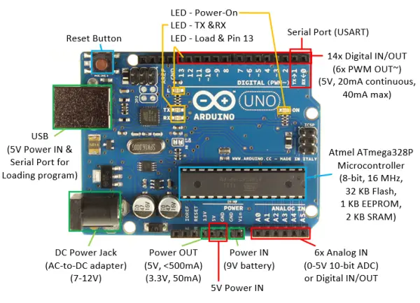
The Arduino UNO board comprises the following key components:
- Microcontroller: It features an Atmel ATmega328P 8-bit microcontroller (acquired by Microchip in 2016) with 32KB of Flash memory for program storage, 2KB of SRAM for data storage, and 1KB of EEPROM for non-volatile data. The microcontroller operates at a clock speed of 16MHz.
- Power Input Options: The Arduino board can be powered through various methods, including:
- USB Connector (5V): This connector serves a dual purpose, providing power and facilitating serial communication with a computer (e.g., for program loading).
- DC Power Jack (7-12V): You can use an AC-to-DC adapter or a battery pack to supply power through this jack.
- Vin/GND Pins (7-12V): Alternatively, power can be provided through these pins using a 7-12V source, such as a 9V battery.
- Power via 5V Supply: While the 5V pin is designed for powering external components, caution is advised when using it to power the Arduino to avoid potential polarity and voltage issues. Using the USB connector for power is a safer option.
- Power Output: The board provides regulated 5V and 3.3V output pins for powering external components. If the board is powered via USB, it can supply a total current of 500mA for both on-board and external use via the 5V power out pin (other power sources provide less current). The 3.3V pin can deliver 50mA.
- On-board LEDs: The Arduino UNO board includes several built-in LEDs for debugging purposes:
- Power-on LED: Indicates that the board is receiving power.
- Load and Pin 13 LED: Flickers during sketch upload and is connected to Digital Pin 13 for program testing and debugging.
- TX and RX LEDs: Indicate communication between the Arduino board and your computer, flickering during sketch upload and serial communication.
- Reset Button: Allows you to reset or restart the program.
- Digital Input/Output Pins: The board provides 14 digital pins (numbered from 0 to 13) that can be configured as inputs or outputs using the
pinMode(0-13, INPUT|OUTPUT)function. You can usedigitalRead(0-13)to read anddigitalWrite(0-13, HIGH|LOW)to write to these pins. Each pin operates at 5V (HIGH) and 0V (LOW) and can provide or receive a maximum current of 40mA, with a continuous current limit of 20mA. The total current for the microcontroller should not exceed 200mA. - PWM Output: Six of the pins (pins 3, 5, 6, 9, 10, and 11, marked with ‘~’) can produce Pulse Width Modulated (PWM) output with the
analogWrite(3|5|6|9|10|11, dutyCycle)function. PWM allows you to generate square wave signals with varying duty cycles, useful for simulating “analog” output to control the brightness of LEDs or the speed of motors. The PWM frequency is 980Hz for pins 5 and 6, and 490Hz for other PWM pins.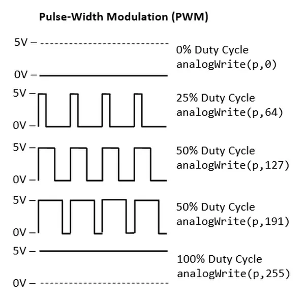
- There are 6 analog input pins labeled A0 to A5 on the Arduino board. By default, each of these pins can measure voltage levels ranging from 0V to 5V with a 10-bit resolution through an analog-to-digital converter (ADC). You can modify the upper range using the AREF pin and the analogReference() function. It’s important to note that these analog pins are distinct from the digital pins, which are numbered from 0 to 13. To work with these analog pins, you can utilize pinMode(A0-A5, INPUT) (which is optional but recommended) and analogRead(A0-A5) to obtain readings in the 10-bit analog input range of [0,1023].While the primary purpose of the analog input pins A0-A5 is to handle analog input, they can also function as digital pins, akin to digital pins 0-13, for both input and output operations. You can employ pinMode(A0-A5, INPUT/OUTPUT) to specify their input/output mode and use digitalRead(A0-A5) or digitalWrite(A0-A5, HIGH|LOW) to read from or write to these pins.Additionally, the Arduino board includes 1 programmable serial port (USART) that can be configured using Digital Pin 0 for RX (receive) and Digital Pin 1 for TX (transmit). Alternatively, you can use the USB connection for communication with a PC, such as for loading programs.Furthermore, there are interrupt capabilities on the Arduino board. Pins 2 and 3 can be employed for “external” interrupts and mapped to INT0 and INT1. All 20 pins (comprising the 14 digital and 6 analog pins) can be utilized for “pin-change” interrupts.
To summarize the key functions related to digital and analog pins:
- pinMode(0-13|A0-A5, INPUT|OUTPUT): This function sets the pin to either INPUT or OUTPUT mode. Digital pins are numbered from 0 to 13, while analog pins are labeled A0 to A5.
- digitalRead(0-13|A0-A5), digitalWrite(0-13|A0-A5, HIGH|LOW): These functions are applicable to all digital and analog pins for reading from or writing to them.
- analogWrite(3|5|6|9|10|11, dutyCycle): This function is specifically for PWM digital pins and allows you to set the duty cycle, ranging from 0 to 255 (0 for low and 255 for high).
- analogRead(A0-A5): This function is used to read a 10-bit input within the range of [0, 1023] for voltage levels between 0V and 5V from the analog input pins.
Lastly, it’s important to consider protective measures to safeguard the Arduino board.
Ensuring Arduino Board Safety:
- A common issue I’ve observed with my students is the rough handling of the Arduino board, which can lead to unintentional short circuits due to exposed connections underneath. To mitigate this risk, you have the option to either acquire a protective casing or employ masking tape to shield the underside of the Arduino board.
- Moreover, it’s advisable to disconnect the power or USB cable from the Arduino board while you’re in the process of connecting or configuring the circuitry. This practice not only safeguards the Arduino but also prevents potential damage to your valuable PC.
Step 1: Acquire the Arduino IDE by downloading it
- Begin by obtaining the Arduino IDE. To do this, visit the Arduino website, select the version that corresponds to your operating system (for instance, Windows or Mac OS X), and retrieve the zip file, such as “arduino-1.8.x-windows.zip.
- Next, extract the contents of the downloaded file into a directory of your preference. For example, you can choose to extract it to “D:\myProject.” This action will result in the Arduino Development Kit being unzipped into “D:\myProject\arduino-1.8.x.” For the sake of this article, we will refer to the installed directory as “$ARDUINO_HOME.” Inside this directory, you will find the Arduino SDK executable named “arduino.exe.”
Step 2: Connect the Arduino Board to Begin Driver Installation (Best of Luck Required!)
- Connect the Arduino board to your computer using the USB cable. You will notice that the “POWER ON” LED illuminates in either green or orange.
- (For Windows) Proceed with driver installation by following these steps:
-
- Open “Control Panel.”
- Access “Device Manager” (right-click and choose “run as administrator”).
- Locate and right-click on the “Unknown device” (or find it under “Ports (COM & LPT)”).
- Select “Update Device Driver.”
- Set the driver location to “$ARDUINO_HOME\drivers,” which corresponds to the unzipped Arduino directory.
- Disregard any warning messages. The device will be recognized as “Arduino Uno (COMxx)” within the “Ports (COM & LPT)” section.
- If your computer fails to detect the board (i.e., there is no unknown device in the previous step), consider the following troubleshooting steps:
-
- Attempt a different USB port.
- Test with another Arduino board.
- Experiment with your Arduino board on an alternative computer.
- And so on… However, refrain from dedicating excessive time to resolving Arduino driver issues
Step 3: Open the Arduino SDK to Begin Crafting Your Initial Program
- Execute “arduino.exe” located in the $ARDUINO_HOME directory.
- Paste the following program (referred to as a “sketch” in Arduino) into the editor panel:
#define BUILTIN_LED_PIN 13    // A Built-in LED connected to digital Pin 13

/*
 * Setup() runs only once for initialization
 */
void setup() {
   pinMode(BUILTIN_LED_PIN, OUTPUT);    // Set Pin 13 (digital) to OUTPUT mode
}

/*
 * loop() repeats forever after setup() completed
 */
void loop() {
   digitalWrite(BUILTIN_LED_PIN, HIGH);  // Set Pin 13 to HIGH (5V) to turn ON its built-in LED
   delay(1000);                  // Delay in msec

   digitalWrite(BUILTIN_LED_PIN, LOW);   // Set Pin 13 to LOW (0V) to turn OFF its built-in LED
   delay(1000);                  // Delay in msec
}
- Select the “Verify” button (or navigate to the “Sketch” menu ⇒ “Verify/Compile”; or use the Ctrl-R shortcut) to compile the code
- Press the “Upload” button (or go to the “File” menu ⇒ “Upload”; or use the Ctrl-U shortcut) to transfer the code to the Arduino board. You should observe the LED beneath Pin 13 blinking in orange, indicating the program is being loaded.
- If you encounter the error message “avrdude: stk500_getsync(): not in sync: resp=0x30,” follow these steps:
- Navigate to the “Tool” menu.
- Access “Serial Port.”
- Choose the appropriate “COMx” port.
- You can confirm the correct COM port by going to “Control Panel” ⇒ “Device Manager” and noting the COM port setting for “Arduino UNO.”
Once the program has been successfully loaded, you will observe the LED located beneath Pin 13 (the same LED used during program loading) alternately illuminating and extinguishing at one-second intervals, continuously.
Dissecting the Program
- An Arduino program, known as a “sketch,” typically consists of a minimum of two functions: “setup()” executes once during startup or after a reset for initialization tasks, while “loop()” runs endlessly after the “setup()” function completes.
- The “pinMode(pinNumber, INPUT|OUTPUT)” function configures the specified “pinNumber” to operate either as an INPUT or OUTPUT.
- With the “digitalWrite(pinNumber, HIGH|LOW)” function, you can set a digital output pin to either a HIGH state (5V) or LOW state (0V). Keep in mind that a digital output pin has a maximum current output of 40mA, with a continuous current limit of 20mA.
- Furthermore, the “#define” directive is resolved during compile-time, potentially reducing the SRAM usage compared to employing a variable.
Examples
Arduino IDE provides many examples, under “File” ⇒ “Examples”, or “File” ⇒ “Sketchbook”.
For example, the above codes can be found under “File” ⇒ “Examples” ⇒ “Built-in Examples” ⇒ “01.Basics” ⇒ “Blink”.
3. Get Set, but Before Go..
3.1 Electronic Tools and Equipment
Essential or Required
Digital Multimeter (A budget-friendly multimeter can be purchased for under $20). Explore online tutorials or YouTube videos to acquire proficiency in using the digital multimeter. Familiarize yourself with the following key functions:
- Measuring Resistance.
- Conducting Continuity Checks.
- Determining DC Voltage.
- Measuring DC Current (in series).
Keep in mind that the primary applications of a digital multimeter involve measuring resistance, DC voltage, and DC current. To visualize waveforms, you would require an oscilloscope.
Toolbox Essentials: Include screwdrivers (both flathead and Phillips), a wire cutter, wire stripper, pliers, a power mains test pen or screwdriver, insulation tape, and masking tape (for labeling and sealing). Also, stock up on 22-Gauge solid wires in various colors, a breadboard, and more.
For Soldering: Equip yourself with a soldering station, complete with a stand, third hand tool, wet sponge, solder sucker, and solder wick. You can either read a tutorial like “How to Solder: Through-Hole Soldering” or refer to online videos for guidance on soldering techniques. If your soldering iron features temperature control, set it to an initial range of approximately 350-370°C.
Note that a breadboard is primarily intended for prototyping purposes. To create your final product, you’ll need to solder components onto a printed circuit board (PCB).
Optional or Beneficial
Desirable Addition:
Consider including a DC Power Supply, such as a 160W Digital Bench Power Supply with adjustable output from 0 to 32V DC and a current range of 0 to 5A. This is particularly valuable as it eliminates the reliance on batteries.
It’s essential to familiarize yourself with the following functions:
- Configuring the desired output DC voltage.
- Setting the output DC current LIMIT to prevent overloading and potential damage.
- Reading and interpreting the displayed voltage and current output values accurately.
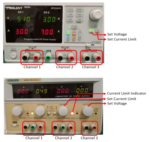
A quality DC power supply typically features two output channels, referred to as “master” and “slave” (some models also include an additional third channel for 5V). These channels can be configured in the following ways:
- Isolated: In this mode, each supply operates as an entirely separate and independent unit. This is the most commonly used configuration.
- Parallel: The output from the slave unit is combined with that of the master unit to increase the overall current capability.
- Series: The positive output terminal of the slave unit is internally connected to the negative output terminal of the master unit.
You can readily read the supply voltage and current values from the control panel. It’s important to closely monitor the current reading to prevent any potential damage to your circuitry.
DC power supplies typically operate in constant-voltage mode, maintaining a stable voltage output. You can set a current limit for the supplies as a safeguard for your circuits. Once the current limit is reached, the supply switches to constant-current mode and will not provide additional current.
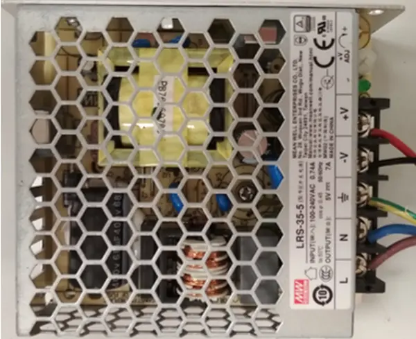
For production purposes, you can obtain cost-effective switching DC power supplies. It’s crucial to know your required voltage (e.g., 5V, 12V) and the maximum current rating (e.g., 3A, 5A, 10A, 50A) when selecting the appropriate supply.
Really NICE to Have
- Oscilloscope
- Function Generato
3.2 Etiquette
Kindly adhere to sound electronic work practices:
- Avoid Metal Contact: Never place the Arduino Board on a metal surface, unless you intend to encounter some unwanted smoke! Apply insulating masking tape underneath or employ an appropriate plastic or wooden enclosure.
- Disconnect Power: Whenever you are making circuit connections, disconnect the power source from the Arduino board to prevent potential short-circuits and the risk of damaging the board.
- Exercise Patience and Methodology: Be patient, systematic, and avoid taking shortcuts in your work.
- Organize Your Workspace: Maintain an organized workbench by storing all components and loose parts in designated containers.
- Follow Color Codes: Recognize the purpose of wire colors. In DC circuits, utilize RED for power and BLACK for ground. Note that color codes are crucial in electronics, and individuals with color blindness may face limitations in this field.
- Use Appropriate Cables and Connectors: Ensure you select the correct cables with the appropriate gauge number and connectors for your specific project.
- Trim Wires Judiciously: Trim your connecting wires to the necessary minimum length for your final product; you’re not angling for fish with them.
- Create Comprehensive Diagrams: Produce well-drawn design diagrams, circuit diagrams, connection diagrams, etc., to facilitate your work.
- Write Effective Programs: Craft high-quality programs and provide comments for your programming statements to enhance clarity.
- Invest in the Right Tools: Remember that the quality of your work is reflected in your toolbox. Obtain and employ the right tools for your tasks
LEDs
I shall follow the exercises in:
- “SparkFun Inventor’s Kit (SIK) Experiment Guide – v4.0” (the latest version at the time of this writing) @ https://learn.sparkfun.com/tutorials/sparkfun-inventors-kit-experiment-guide—v40/introduction.
- The older version of “SparkFun Inventor’s Kit (SIK) Guide for Arduino” @ https://www.sparkfun.com/products/retired/11227, with PDF User’s Guide @ http://cdn.sparkfun.com/datasheets/Kits/SFE03-0012-SIK.Guide-300dpi-01.pdf.
- “Oomlout’s Arduino Experimentation Kit (ARDX)” @http://www.oomlout.com/a/products/ardx/.
I shall provide more technical explanation and computation for my engineering students. You need the hardware components to do these exercises. I suggest you purchase an “Arduino Starter Kit” which comes with common electronic components
LED Ex 1: Blinking LED (with a Current Limiting Resistor)
Reference: “SIK Circuit 1A: Blink an LED” or “Oomlout CIRC01 Getting Started”
Goal: To create a repeating LED blinking sequence with a one-second interval.
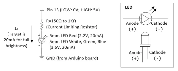
Required Components: 1x LED (5mm, Red, or White) – Be mindful of LED polarity. The shorter leg featuring a flat side signifies the cathode (-), while the longer leg corresponds to the anode (+). It’s advisable to be proficient in using a digital multimeter for checking diode polarity. 1x 330Ω resistor
Circuit Diagram

Program
Execute the program located in “$ARDUINO_HOME\examples\01.Basics\Blink\Blink.ino,” or use the one provided below:
/*
 * Blink: Turns ON an LED on for one second, then turn OFF for one second, repeatedly.
 */
#define LED_PIN 13   // Give it a name for easy referencing

/*
 * setup() run once for initialization
 */
void setup() {
   pinMode(LED_PIN, OUTPUT);  // initialize the digital pin as output
}

/*
 * loop() repeats forever after setup() completes
 */
void loop() {
   digitalWrite(LED_PIN, HIGH);  // turn the LED ON by making the voltage HIGH (5V)
   delay(1000);                  // wait for the given millisecond

   digitalWrite(LED_PIN, LOW);   // turn the LED OFF by making the voltage LOW (0V)
   delay(1000);                  // wait for the given millisecond
}
- An Arduino program, known as a sketch, comprises a minimum of two functions: setup() and loop(). The setup() function executes once during startup or after a reset, primarily for initialization tasks. Conversely, the loop() function runs indefinitely after the setup() completes.
- In the program’s initialization phase (inside setup()), Pin 13 is configured as an OUTPUT by employing the pinMode() function. This pin can subsequently produce either a digital HIGH (5V) or LOW (0V) signal. Following this initialization, the program sets Pin 13 to HIGH (5V), introduces a 1000-millisecond delay (1 second), toggles Pin 13 to LOW (0V), and adds another 1000-millisecond delay. This sequence repeats continuously within the loop() function.
Dissecting the Circuit for Engineering Students
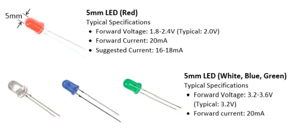
- In contrast to resistors, LEDs exhibit non-linear behavior and do not adhere to Ohm’s law. LEDs are regarded as current-driven devices with a consistent voltage drop. To achieve maximum brightness in a standard 5mm LED, it is recommended to maintain a forward current of 20mA
- In practical design applications, we typically consider the forward voltage of LEDs as fixed at 3.6V (applicable to white, blue, and green LEDs) or 2.2V (as indicated in the datasheet for red LEDs).
- We must select a resistor, denoted as R and referred to as the current-limiting resistor, in a manner that ensures a current of IL=20mA flows through both the resistor and the LED. Assuming a 5V supply voltage (where digital pin 13 outputs 5V when set to HIGH), the calculations are as follows:For white, green, or blue LEDs: R = (5-3.6)V / 20mA = 70Ω For red LEDs: R = (5-2.2)V / 20mA = 140Ω (as specified in the datasheet)Opting for a higher resistor value will result in reduced current, leading to a dimmer LED or no illumination at all. Conversely, selecting a lower resistor value will increase the current, potentially wasting power and risking damage to the LED. In engineering design, this initial R value serves as a starting point. You can then assess the brightness, measure voltage and current, and subsequently fine-tune the resistor value as needed.
- The LED’s power consumption amounts to 72mW (for white, green, and blue LEDs) or 44mW (for red LEDs) when you calculate it as 20mA multiplied by 3.6V or 2.2V, respectively. The cumulative power consumed by the LED at 20mA current and 5V supply voltage is 100mW
- It’s important to be aware that the digital output pins of the Arduino can deliver a maximum current of 40mA (or a continuous current of 20mA). This level of current is suitable for driving 1-2 LEDs in parallel, each at 20mA. However, it’s not adequate to power more than two LEDs to their maximum brightness.
- When two LEDs are connected in series, the combined voltage drop ranges from 4.4V to 7.2V (calculated as 2.2 to 3.6V each multiplied by 2). It’s important to note that a 5V power supply cannot effectively operate more than two LEDs in series. In scenarios where three LEDs are arranged in series, such as in certain LED strips, a 12V supply is commonly employed.
Practices for Engineering Students
LEDs sourced from various manufacturers may come with varying specifications, including forward current and forward voltage ratings. Furthermore, you might encounter situations where it’s challenging to locate the precise datasheet for a specific LED. In such cases, the best approach is to rely on your trusty multimeter to measure these parameters yourself.
Please take note: If you have only been provided with a 330Ω resistor, you have the option to create a parallel connection of two resistors to achieve a total resistance of 165Ω (following Ohm’s law). Alternatively, you can connect three of them in parallel to obtain a resistance of 110Ω.
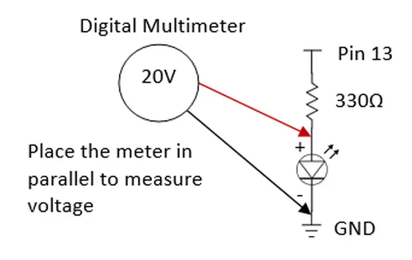
- Set pin 13 to the HIGH state (to activate the LED):
- Utilize a digital multimeter to gauge the voltage at pin 13 and across the LED. For voltage measurement, position the meter in parallel, following the provided illustration, and configure it to measure either 20V or employ the auto-range function.
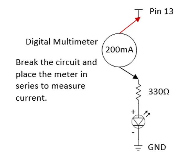
- Utilize Ohm’s law to calculate the current passing through the resistor, which is the same current flowing through the LED.
- With a digital multimeter, gauge this current and subsequently compare it to the calculated value. For measuring current, INTERRUPT the circuit and position the meter in SERIES, following the provided illustration, then set the meter to measure either 200mA or employ the auto-range function.
Answer:
- For a white LED paired with a 330Ω resistor, the measured LED forward voltage is 2.77V, and the measured forward current is 5.9mA. The calculated IL = (5 – 2.77) / 330 = 5.75mA.
- For a white LED with a 165Ω resistor, the measured LED forward voltage is 2.85V, and the measured forward current is 10.6mA. The calculated IL = (5 – 2.85) / 165 = 13mA.
- For a red LED with a 330Ω resistor, the measured LED forward voltage is 1.90V, and the measured forward current is 8.4mA. The calculated IL = (5 – 1.90) / 330 = 9.3mA.
- For a red LED paired with a 165Ω resistor, the measured LED forward voltage is 1.95V, and the measured forward current is 15mA. The calculated IL = (5 – 1.95) / 165 = 18.5mA.
- It’s important to note that the measured forward voltages remain relatively constant, while the forward current and LED brightness exhibit variations.
Switch pin 13 to the LOW state (to deactivate the LED) and carry out the preceding measurements once more.
Replicate these measurements for RED, WHITE, GREEN, and BLUE LEDs.
Perform the same measurements for a configuration involving two LEDs in parallel.
Redo the measurements for a setup with two LEDs in series.
Repeat the measurements once more, this time with three LEDs connected in parallel.
LED Exercise 1a: Change the Blinking Time
To alter the frequency of the blinking, you have the option to adjust the delay, which is currently configured at 1000 milliseconds (or 1 second)
LED Ex 2: Controlling the Brightness of a Single-Color LED via PWM
To manage the LED’s brightness, utilize pin 9 instead of pin 13. Pin 9 can generate a Pulse Width Modulation (PWM) square wave through the analogWrite(pinNumber, dutyCycle) function (refer to the PWM Tutorial). The dutyCycle parameter determines the duration of the ON state in the square wave, with values ranging from 0 (always OFF) to 255 (always ON).
Experiment with the subsequent program:
#define LED_PIN 9       // LED connected to digital PWM pin 9
#define DUTY_CYCLE 192  // Duty cycle for the PWM over [0,255]

/* Setup() runs only once */
void setup() {
   pinMode(LED_PIN, OUTPUT);  // Set to OUTPUT mode
}

/* loop() repeats forever */
void loop() {
   analogWrite(LED_PIN, DUTY_CYCLE);  // Try other values from 0 to 255
   delay(1000);                       // time delay in msec before repeat

   // Fade in from min to max in increments of 5
   for (int fadeValue = 0 ; fadeValue <= 255; fadeValue += 5) {
      analogWrite(ledPin, fadeValue);
      delay(30); // small delay to see the effect
   }

   // Fade out from max to min in decrements of 5
   for (int fadeValue = 255 ; fadeValue >= 0; fadeValue -= 5) {
      analogWrite(ledPin, fadeValue);
      delay(30);
   }
}
The LED’s luminance corresponds to the duty cycle, with the ON duration determining its brightness. For instance, if the duty cycle is set to 64, the LED will shine at 25% of its maximum brightness
LED Basics
An LED (Light Emitting Diode) is fundamentally a diode.Diodes allow the passage of current in the forward direction, going from the anode to the cathode, but not in the reverse direction.
- When current flows in the forward direction, it moves from the anode to the cathode, resulting in the emission of light (although ordinary diodes emit only a small amount of light). The voltage and current applied to the diode in this direction are referred to as forward voltage and forward current, respectively. The forward voltage typically falls within the range of 0.7V to 1.0V.
- Conversely, in the reverse direction, the diode permits little to no current flow, or at most a minimal leakage current
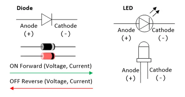
LEDs exhibit a considerably higher forward voltage when compared to typical diodes. While a standard diode typically features a voltage drop ranging from approximately 0.7V to 1.0V, LEDs can have significantly higher voltage drops, ranging from 2.2V for Red LEDs to 3.6V for Green, Blue, and White LEDs. This discrepancy arises because LEDs are constructed using semiconductor materials other than silicon (as it’s challenging to induce silicon to emit light). Instead, materials like AlGaInP, InGaN, and InGa1N are employed. It’s worth noting that white, green, and blue LEDs exhibit higher forward voltage values than their red counterparts.
A standard 5mm LED typically operates with a forward current of 20mA, resulting in power consumption ranging from 44mW to 72mW, depending on the specific LED with forward voltage in the range of 2.2V to 3.6V.
LEDs are Current Devices
A resistor is a linear component that adheres to Ohm’s law, which states V = I * R.
A diode operates as a non-linear component, deviating from Ohm’s law. The relationship between forward current (If) and forward voltage (Vf) is exponential, expressed as If = I0 * exp(k * Vf) or Vf = (1/k) * ln(If/I0). Due to this exponential relationship, doubling the forward current (If) results in only a marginal increase in the forward voltage (Vf). Consequently, in practical applications, we can assume a constant forward voltage (Vf), such as 2.2V for red 5mm LEDs or 3.6V for green, blue, and white 5mm LEDs, regardless of the forward current (If). Essentially, diodes are treated as current-controlled devices, where we regulate the current to achieve the desired performance (e.g., 20mA for full brightness in a 5mm LED). Furthermore, since voltage remains constant, power consumption is also solely determined by the current (e.g., 4.4mW for red LEDs or 7.2mW for white LEDs).
Classes of LEDs
LEDs can be classified into two classes:
- Small devices, usually in the form of 5mm (or T1 3/4) components, operate at a standard current of 20mA. They serve as indicators in various applications, such as cell phone backlights, flashlights, road signage, truck taillights, traffic lights, automobile dashboards, and more. For instance, a typical 5mm white LED, with a forward current of 20mA and a forward voltage of 3.6V, consumes power at a rate of 72mW. To create a 1W flashlight, you would need 14 of these LEDs, and for a 14W fluorescent bulb replacement (when comparing wattages, without considering lumens), you would require 194 of them.
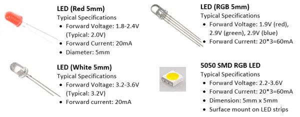
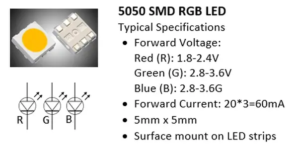
In LED strips, you’ll encounter surface-mount 5050 RGB LED modules, each featuring three LEDs in red, green, and blue. These modules require a total of 60mA (3x20mA) to achieve full white illumination.
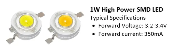
- Power devices, typically ranging from 1 to 3 watts, operate at a current of 350mA. These components are employed for illumination purposes rather than as indicators. They find application in various scenarios such as flashlights, replacements for incandescent bulbs or tubes, large-screen TVs, projector lights, automotive headlights, airstrip runway lighting, and more.
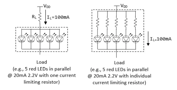
Controlling LEDs with High Current Using Power Transistors
As previously stated, an Arduino’s digital pin can provide a maximum output current of 40mA (or 20mA continuously). It’s not suitable for driving more than two LEDs rated at 20mA in parallel. Additionally, the digital pin outputs 5V, making it unsuitable for driving 3 LEDs in series (2.2V*3=6.6V). If our goal is to control multiple LEDs in parallel using a single Arduino digital output pin, we must employ an external power supply and a power transistor switch capable of handling higher currents.
Choosing a Power Transistor
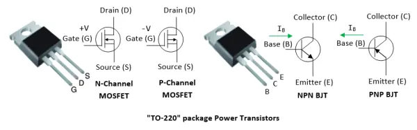
In LED applications, we usually opt for a “TO-220” package power transistor with a 1W power dissipation capability, as illustrated below. If necessary, you can affix an external heat sink.
There are two categories of transistors:
- Bipolar Junction Transistors (BJT): BJT comprises three terminals designated as Base (B), Emitter (E), and Collector (C). BJT operates as a current-controlled device, with the Base current regulating the current flowing between the Collector and Emitter. There are two variations of BJT: NPN and PNP. They share identical structures, differing only in polarity.
- Metal Oxide Semiconductor Field-Effect Transistor (MOSFET): MOSFET, too, consists of three terminals denoted as Gate (G), Source (S), and Drain (D). Unlike BJT, MOSFET functions as a voltage-controlled device, where the Gate voltage governs the current passing between the Source and Drain. MOSFET comes in two types: n-channel and p-channel.
In contemporary electronics, MOSFETs are prevalent for high-power applications due to their superior power handling efficiency. BJTs, on the other hand, continue to be employed for low-current tasks, such as switching, owing to their cost-effectiveness.
For examples,
- IRLB8721PbF N-channel Power MOSFETs (Datasheet) are capable of toggling 30V at 16A (equivalent to controlling 750 LEDs at 20mA) using signals of 3.3V and 5V. They can dissipate up to 2 watts (400mA at 5V) without requiring a heat sink, operating efficiently at room temperature.
- The IRF630 N-Channel Power MOSFET is designed to switch 200V at 9A with a VGS of 20V. Similarly, the IRF520 N-Channel Power MOSFET can handle 100V at 9A.
- For NPN Epitaxial Darlington Transistors, the TIP120/121/122 series (Datasheet) offers the capability to switch 60/80/100V at 5A, making them suitable for controlling up to 250 LEDs at 20mA each.
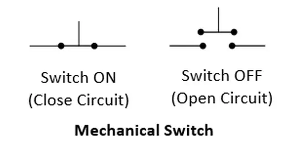
Transistor as an Electronic Switch
A transistor has the versatility to operate either as an amplifier in its active mode or as a switch in its saturation mode.
In this section, our primary focus will be on using a transistor as a switch. Much like a mechanical switch that you push to close a circuit and push again to open it, a transistor can function as an “electronic” switch
N-Channel MOSFET as a Switch
An N-channel MOSFET can act as an active-high voltage-controlled switch. When you apply a HIGH voltage to the Gate (G), it connects (switches on) the Drain (D) and Source (S). Conversely, when you set the Gate (G) to LOW, it disconnects (switches off) the Drain (D) and Source (S), as shown in the illustration.
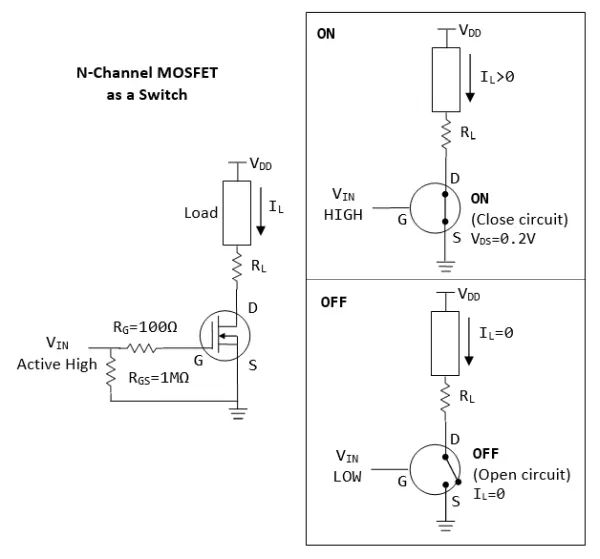
- The n-channel MOSFET turns on when VGS (Gate-Source Voltage) is greater than VTH (threshold voltage).
- When the transistor is switched on by setting VIN (Gate voltage) to HIGH, the voltage drop across the MOSFET, VDS (Drain-Source Voltage), is approximately 0.2V, and the current through it, IL, is controlled by the current limiting resistor RL. For example, if the load requires 2.2V and 350mA, and the supply voltage is VDD = 5V, you can calculate RL as (5V – 2.2V – 0.2V) / 350mA = 7Ω.
- When the transistor is switched off by setting VIN to LOW, IL becomes 0, effectively cutting off the current.
- It’s possible to interchange the positions of RL and the load in the circuit.
- MOSFETs have an extremely high input resistance, almost infinite, making them compatible with nearly any logic gate or driver.
- To ensure reliable switching, it’s common practice to include a high-value resistor RGS (ranging from 10KΩ to 1MΩ) between the gate and source. This resistor serves to discharge any electric charge on the gate and turn off the MOSFET. Without it, very small currents from sources like your finger, capacitive coupling, or inductive coupling could inadvertently change the gate voltage.
- The inclusion of the gate resistor RG is optional. A small resistor (around 100Ω) can be used to prevent ringing in the circuit by damping oscillations.
Let’s consider that we are powering the following load:

Suppose that VDD=5V, RL=(5-2.2-0.2)V/100mA=26Ω.
P-Channel MOSFET as a Switch
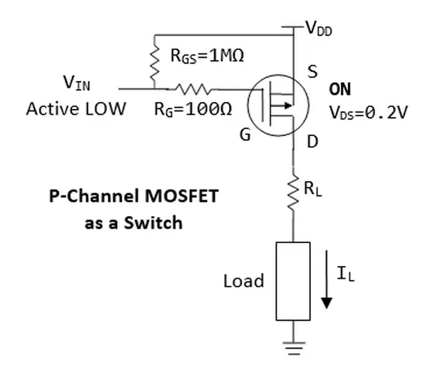
Much like the N-channel MOSFET, the P-channel MOSFET exhibits:
Operating in an active LOW configuration, the P-channel MOSFET turns on when Vin equals 0V or when VSG exceeds its threshold voltage (VTH). You have the option to connect one terminal of the load to the ground.
The P-channel MOSFET serves as a “high-side” switch, a less commonly used choice compared to the “low-side” switch configuration typically employed with N-channel MOSFETs. In the case of N-channel MOSFETs, the Source (S) is linked to ground, while for P-channel MOSFETs, the Source (S) connects to VDD.
NPN BJT as a Switch
To enable the connection (switching on) between the collector (C) and emitter (E) in an NPN transistor, you raise the base (B) to a high voltage level, ensuring that IB (base current) exceeds the threshold current (ITH). Conversely, you deactivate (switch off) the connection between the collector (C) and emitter (E) by lowering the base (B) to a low voltage level.
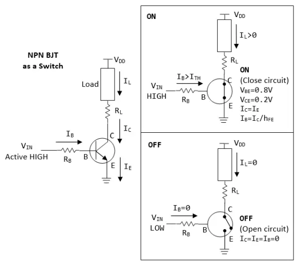
When an NPN transistor is in its saturation mode, it operates as an electronic switch controlled by current:
- When a modest base current (IB) exceeding the threshold current (ITH) is applied, the transistor activates, allowing current to flow through the collector, emitter, and consequently, the connected load.
- Conversely, when IB equals zero, the transistor deactivates, causing no current to pass through the collector, emitter, or the load.
You may switch the position of the RL and the load
To activate an NPN transistor, we set VIN to a high level, typically 5V, allowing a base current (IB) to flow from the base to the emitter. When the transistor is turned on, we can consider VBE as approximately 0.8V and VCE as about 0.2V. This simplification treats diodes as current-controlled devices with relatively constant voltage drops.
Let’s assume VDD is 5V, and we want to achieve a load current (IL) of 100mA. Using Ohm’s law, we calculate the load resistor (RL) as follows: RL = (5V – 2.2V – 0.2V) / 100mA = 26Ω.
To determine the base resistor (RB), we use the relationship IC = hFE * IB, where hFE represents the transistor’s current gain, typically lower in the saturation region compared to the active region. Let’s assume hFE is 10 (or 20) for saturation. If VIN is 5V, we can calculate RB as follows: RB = (5V – 0.8V) / (100mA / 10) = 420Ω.
If the transistor fails to turn on, consider using a lower resistance value for RB. It’s important to note that these values serve as initial approximations for your design, and it’s advisable to fine-tune them by measuring voltages and currents with a multimeter.
We can turn OFF an npn transistor by setting VIN to low (0V). In this case, IB=0, results in IC=0
PNP BJT as a Switch
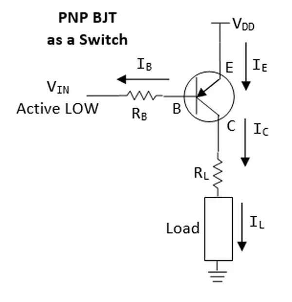
- Active low (instead of active high for NPN).
- “high-side” switch (instead of “low-side” switch for NPN).
- One terminal of load can be connected to ground (instead of one terminal to VDD for NPN).
- Emitter connects to VDD (instead of Ground for NPN)
Exercises
Utilize either an NPN Bipolar Junction Transistor (BJT) or an N-channel Metal-Oxide-Semiconductor Field-Effect Transistor (MOSFET) to control a parallel configuration of five LEDs. Employ a multimeter to measure both the currents and voltages in the circuit.
LED Strips
An LED strip, also referred to as LED tape or ribbon light, consists of a flexible circuit board adorned with surface-mounted LEDs, like the 5050 SMD RGB LED module, along with additional components. Typically, these strips feature an adhesive backing, and some are designed to be waterproof, suitable for outdoor use.
LED strips can be categorized into the following types:
- In the non-addressable (or analog) type, individual LED control is not possible, and all LEDs display the SAME color uniformly.
- In the addressable (or digital) type, every segment incorporates a Driver IC chip that includes latches and shift registers. By transmitting digitally coded data serially to these chips through the Data-In (DI) and optionally the Clock-In (CI) connections, you gain the capability to individually control the color of each LED within the segments. However, it’s worth noting that addressable LED strips tend to be more costly.
An LED strip is constructed from uniform segments, each of which incorporates 1 to 3 LED modules, along with their respective current-limiting resistors. All these segments are connected in parallel for power supply. LED strips generally function at either 12V (when there are 3 LED modules connected in series per segment) or 5V (when only one LED module is in each segment). This voltage configuration is necessary because an individual LED typically requires a forward voltage of 2.2-3.6V, and 5V isn’t adequate to power multiple LEDs in series.
Every red, green, and blue LED consumes 20mA of current. Consequently, when producing a full white color, they collectively require 60mA. In the case of a 20-RGB-module per meter configuration, this translates to a substantial power draw of 1.2A per meter.
It’s essential to emphasize that attempting to power the LED strips directly from the Arduino board is not feasible since the board can supply only up to 500mA, which falls significantly short of the required current. To properly power these LED strips, you must connect them to an external power supply.
Non-Addressable (Analog) 12V RGB LED Strip
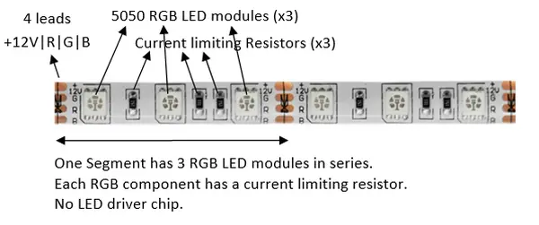
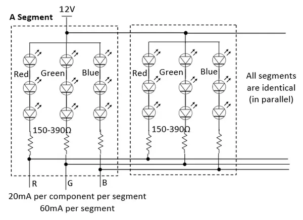
There are four leads labeled as +12V, G, R, and B in the configuration. Within each segment, three 5050 RGB LED modules are linked in series, with a common anode (+) connected to the +12V lead. Additionally, each component includes a current-limiting resistor, typically falling in the range of 150-390Ω. All these segments are interconnected in parallel.
Considering that the forward voltage of an LED varies between 2.2-3.6V, when three LEDs are arranged in series, they collectively require 6.6-10.8V. Consequently, to effectively power three LEDs in series, a power supply voltage of 9-12V is essential. Each LED module draws a current of 20mA.
The maximum current for each strip segment is capped at 12V and 60mA. In the case of segments spaced 50mm or 100mm apart, corresponding to 20 or 10 segments per meter, the maximum current load is 1.2A per meter. However, based on my personal measurements, a 20-segments-per-meter RGB LED strip draws approximately 970mA when supplied with 12V, and 370mA when operated at 9V, which still provides sufficient brightness.
Transistor Driver
To operate the LED strip effectively, an external power supply is required. Additionally, three power transistors, such as N-channel MOSFETs or NPN BJTs, are necessary to manage the current for each of the RGB components, as outlined below. The Arduino pins are connected to RIN, GIN, and BIN to enable the control of the RGB LEDs, turning them on or off as needed.
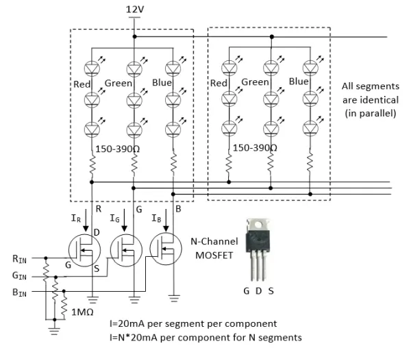
Arduino Connection
- Connect
RIN,GINandBINto Arduino pins; - Connect the 12V/GND to power supply;
- Connect the GND from power supply to arduino (to establish common ground).
To control the brightness and color of the LEDs, you can use PWM output to drive RIN, GIN and BIN to turn on/off the LED at the specified duty cycle
Addressable (Digital) RGB LED Strip
Certain addressable LED strips come equipped with four leads, denoted as GND/DI/CI/+5|12V or GND/DO/CO/+5|12V. In this context, DI and CI signify “Data-In” and “Clock-In,” while “DO” and “CO” represent “Data-Out” and “Clock-Out.” It’s essential to establish connections with the “IN” end of the strip. The “OUT” end is reserved for daisy-chaining to the “IN” end of another strip in a cascading configuration.
For each segment, there is an LED driver clip that incorporates latches and shift registers. Data is transmitted through the shift registers via the DI (Data-In) connection, utilizing the CI (Clock-In) signal for synchronization. The initial LED driver reads the first 24 bits of data (comprising 8 bits each for Red, Green, and Blue) from DI, while the subsequent LED driver processes the next 24 bits, and so forth.
In the case of some addressable LED strips, they feature only three leads, omitting the CI (Clock-In) connection. In such instances, you must send the coded data with precise timing through DI, typically at frequencies of 800kHz or 400kHz.
Addressable LED strips are available in both 12V and 5V variants. In the 12V version, each segment accommodates 3 LED modules connected in series. Conversely, for the 5V version, there is only one LED module per segment. This distinction arises because individual LEDs typically necessitate a forward voltage of 2.2-3.6V, rendering a 5V supply incapable of powering more than one LED in series.
Establishing a connection with an addressable LED strip is a simple process:
- Directly link the LED strip’s +12V/+5V and GND to an external power source.
- Establish a connection by attaching DI and CI to any of the digital pins on the Arduino.
- Create a common ground by connecting the ground (GND) of the power supply with the ground (GND) of the Arduino.
Streamline your programming tasks with the help of specialized library code. Two widely used libraries for programming addressable LED strips, NeoPixel and FastLED (compatible with both 3-wire and 4-wire chipsets), will be discussed in detail below.
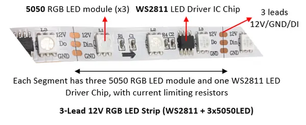
3-Lead 12V RGB Addressable LED Strip (WS2811) / 3-Lead 5V RGB Addressable LED Strip
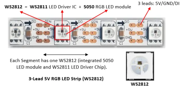
- The WS2812 comprises an integrated package featuring a WS2811 LED driver IC chip combined with a 5050 RGB LED within each segment. The 5050 is a compact surface-mount module housing three RGB LEDs in a single 5mm x 5mm case. This configuration is designed to operate with a 5V power supply. The WS2812B represents an enhanced iteration of the WS2812.
- The 12V RGB LED strips consist of three 5050 LED modules and a distinct WS2811 LED driver IC chip that is not integrated with the 5050 LEDs. This setup requires a 12V power source to effectively power the three LEDs arranged in series.
- In the case of the WS2812 5V RGB LED strip, which has only one LED per segment with a forward voltage ranging from 2.2-3.6V, it can be effectively powered using a 5V supply. The maximum current consumption per segment amounts to 60mA, accounting for 3x20mA per RGB LED. For a 60-segment per meter LED strip, the total maximum current draw reaches 3.6A (60mA * 60 segments). To accommodate this, it’s imperative to employ an external 5V power supply rather than relying on the Arduino board to deliver the required current.
- In the case of the WS2811 12V RGB LED strip, the maximum current load per segment also amounts to 60mA. When considering a strip with 20 segments per meter, it results in a current draw of 1.2A per meter.
- The WS2812/WS2811 LED strip utilizes a 3-wire configuration comprising +5V|+12V, GND, and Data-In (DI), without the need for a Clock-In (CI) wire. The WS2811 controller internally generates the clock signal, obviating the requirement for a separate CI connection. Instead, you must transmit the serial coded data through the DI wire with precise timing, typically set at 400kHz or 800kHz.
- Connecting the strip to Arduino is simple:
- Connect +5V|+12V and GND to an external power supply.
- Connect the power supply’s GND to Arduino’s GND.
- Connect the DI to any Arduino’s digital pin.
To program WS2811 LED drivers, you typically need to cascade the 24-bit RGB color code for each pixel down the DI line until it reaches its designated location, adhering to specific timing requirements. However, this process has been significantly streamlined through the utilization of library codes. There are two widely recognized libraries for programming addressable LED strips: NeoPixel and FastLED, both of which will be detailed below.
NeoPixe
You need to customize these lines:
#include <Adafruit_NeoPixel.h>
#define DATA_PIN 6       // Data-In (DI) connects to this pin
#define NUM_LEDS 60
Adafruit_NeoPixel strip = Adafruit_NeoPixel(NUM_LEDS, DATA_PIN, NEO_GRB + NEO_KHZ800);
In setup():
void setup() {
   strip.begin();  // initialize strip's buffer to all zeros (off)
   strip.show();   // Update all LEDs
}
You can then play with the color in loop():
// Set the color of a particular LED via setPixelColor()
uint32_t color = strip.Color(255, 0, 0);  // Set R, G and B of a color
strip.setPixelColor(8, color);            // Set LED 8's color
strip.show();                             // Update ALL LEDs
delay(1000);

// You can retrieve the color of a LED via getPixelColor()
strip.setPixelColor(9, strip.getPixelColor(8));
strip.show();                             // Update ALL LEDs
delay(1000);

// To switch an LED off use the color BLACK (0,0,0)
strip.setPixelColor(8, strip.Color(0,0,0));  // Set LED color
strip.show();                                // Update all LEDs
delay(1000);

// Set all LEDs to green
color = strip.Color(0, 255, 0);
for (int i = 0; i < strip.numPixels(); ++i) {
   strip.setPixelColor(i, color);
}
strip.show();    // Update all LEDs
delay(1000);
Execute and examine the remaining examples.
NeoPixel utilizes a display buffer that corresponds to all the LEDs within the strip. To configure this buffer, you are required to invoke strip.begin(). You can modify the color within the buffer using strip.setPixelColor(index, color), and when you are ready to update the strip’s LEDs, you can activate strip.show() to transmit all the values from the buffer to the strip.
Color is expressed as a uint32_t, encompassing the red, green, and blue components.
strip.Color(R, G, B): translate the R, G and B into a color value in auint32_t.strip.setPixelColor(pixelIndex, color): set the color of a particular pixel.strip.getPixelColor(pixelIndex): returns a 32-bit color value of a particular pixel.strip.numPixels(): returns the number of pixel declared during initialization.strip.setBrightness(level): adjust the brightness of all the LEDs withlevelranges from 0 (off) to 255 (max brightness).setBrightness()was intended to be called once, insetup(), to limit the current/brightness of the LEDs throughout the life of the sketch. It is not intended as an animation effect itself!
FastLED 3.1
FastLED is compatible with both 4-wire and 3-wire chipsets, whether or not they include a Clock-In (CI). You are required to tailor these connections:
#include "FastLED.h"
#define NUM_LEDS 60    // Number of LEDs in your LED strip
#define DATA_PIN 6     // Data-In (DI) connecting to this pin

// For four-wire chipsets with a Clock-In (CI) only
//#define CLOCK_PIN 7    // Clcok-In (CI) connecting to this pin

// Define an array of LEDs to keep the RGB values of each LED
CRGB leds[NUM_LEDS];
In setup():
void setup() {
   // For 3-wire chipsets without Clock-In (CI)
   FastLED.addLeds<NEOPIXEL, DATA_PIN>(leds, NUM_LEDS);  // or set to WS2812 or WS2811
   ....
   // For 4-wire chipsets with a Clock-In (CI)
   //FastLED.addLeds<LPD8806, DATA_PIN, CLOCK_PIN>(leds, NUM_LEDS);
}
You can then play with the color in loop():
// To switch an LED Off, set the color to Black for that particular LED and call the show() function:
leds[8] = CRGB::Black;  // Array index begins at 0, up to NUM_LEDs - 1
                        // Set color to black via pre-defined constant CRGB::Black
FastLED.show();         // Show changes

// Set an LED to a specific color
leds[8] = CRGB::Red;    // Set LED 8 to red via pre-defined constant CRGB::Red
FastLED.show();         // Show changes
delay(1000);

// You can set each of the RGB components individually
leds[18].r = 255;     // Set red component, value between 0 and 255
leds[18].g = 125;     // Set green
leds[18].b = 0;       // Set blue
FastLED.show();       // Show changes, no change in leds[8]
delay(1000);

// Set all LEDs to pre-defined constant ForestGreen (0x228B22)
for (i = 0; i < NUM_LEDS; ++i) {
   leds[i] = CRGB::ForestGreen;
}
FastLED.show();       // Show changes
delay(1000);
Motors
Circuit Diagram
Dissecting the Circuit
In the circuit described above, we employ a P2N2222AG NPN BJT transistor with a maximum rating of 40V and 200mA (as detailed in the datasheet) as an electronic switch. This transistor turns on when pin 9, connected to its base (b), produces a HIGH signal at 5V. The base current (IB) is calculated as (5V – 0.8V) / 330Ω, resulting in 13mA. When turned on, there is a voltage drop of 0.2V across the collector (c) and emitter (e) of the transistor. Conversely, the transistor is in the OFF state when pin 9 outputs a LOW signal (0V).
In this setup, a transistor is essential because the output from pin 9, with a maximum current of 40mA, is inadequate to directly power the DC motor. However, only a small amount of current (2mA) is required to activate the transistor.
The rotation speed of a DC motor is directly proportional to the applied voltage when there is no load. As a load is introduced, the speed decreases, and the current drawn by the motor also correlates with the torque it produces.
DC motors come in a variety of specifications. For instance, one toy DC motor is designed to operate within a voltage range of 1.5V to 4.5V, and under no load, it can reach a speed of 23,000 RPM when powered at 4.5VDC, drawing a current of 70mA (as per the datasheet). Another toy DC motor is suitable for operation in a voltage range of 1.0V to 3.0V and achieves a no-load speed of 6,600 RPM when supplied with 1.0V DC, consuming a current of 110mA (according to the datasheet).
In general, DC motors like these typically require around 100mA of current to function correctly, a current level that cannot be provided directly from an output pin on devices like the Arduino, which has a maximum current output of 40mA. The transistor used in this setup has a rating of 200mA, which comfortably accommodates the motor’s current requirements.
Practice
Connect the DC motor directly to 5V. Measure the no load current.
Set pin 9 to HIGH (to turn on the transistor):
- Using a digital multimeter, measure the voltage at pin 9, the voltage across the base and emitter VBE. Compute the base current IB (through the base resistor).
- Measure the voltage across the collector and emitter VCE.
- Measure the collector current IC
Arduino Mega 2560
The Arduino UNO has its constraints, such as its ability to drive approximately 300-400 LED pixels due to its 2KB of SRAM and its limited number of available I/O pins. Many of your projects might demand the capabilities of a more robust microcontroller, such as the Arduino Mega 2560, which has superseded the original Arduino Mega model.
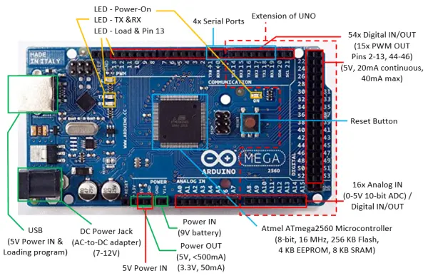
Arduino Mega 2560 has:
- 54 digital I/O pins, of which 15 can be used as PWM outputs (pins 2-13, 44-46). Each pin could provide 20mA current. (Compared with Arduino UNO: 14 digital pins, 6 PWMs.)
Use functionpinMode(0-53, INPUT|OUTPUT)to configure the pin for input or output; anddigitalRead(0-53)ordigitalWrite(0-53, HIGH|LOW)to read or write.
For PWM pins, you can use functionanalogWrite(2-13|44-46, dutyCycle)with duty cycle of between 0 (off) to 255 (on) to output PWM signal. - 16 analog input pins. (Compared with Arduino UNO: 6)
Use functionpinMode(A0-A13, INPUT)(optional but nice to have) andanalogRead(A0-A13)to read the 10-bit analog input[0,1023].
These analog input pins can also be used for digital input/output like the digital I/O pins, with pin number for A0-A13. - 4 Serial ports (USART) (Compared with Arduino UNO: 1).
- ATmega2560 microcontroller @ 16MHz, with 256KB of Flash memory for program, 8KB of SRAM for data, and 4KB of EEPROM for non-volatile data.
More on Arduino
Microcontroller
The Arduino UNO is powered by the ATmega328P microcontroller, boasting the following attributes:
- A low-power CMOS 8-bit microcontroller founded on the AVR enhanced RISC architecture.
- Utilizes an advanced RISC Architecture featuring 131 instructions, with most executing in a single clock cycle.
- Equipped with 32×8 general-purpose registers.
- Offers up to 20 MIPS throughput at 20MHz.
- Provides 32 KBytes of Flash memory for program storage with 10,000 write/erase cycles.
- Includes 1 KBytes of EEPROM memory capable of 100,000 write/erase cycles.
- Contains 2 KBytes of SRAM.
- Features six PWM channels.
- Equipped with a 6-channel 10-bit ADC.
- Offers one programmable Serial USART.
- Provides two Master/Slave SPI Serial Interfaces.
- Includes one Byte-oriented 2-wire Series Interface (I2C compatible).
- Features two 8-bit Timer/Counters with separate prescalers and compare modes.
- Includes one 16-bit Timer/Counter with separate prescalar, compare mode, and capture mode.
- Supports interrupt and wake-up on pin change.
- Has an operating voltage range of 1.8V to 5.5V.
- Exhibits a power consumption of 0.2mA in Active Mode @ 1MHz, 1.8V, 25°C.
The Arduino Mega2560, on the other hand, is powered by the ATmega2560 microcontroller, which is an 8-bit microcontroller.
Memory
Types of Memory
The Arduino board comprises three distinct memory pools:
1. **Flash Memory:** This space is dedicated to storing the program, often referred to as program space. Both Flash and EEPROM memory are non-volatile, meaning the data remains intact even when the power is turned off.
2. **SRAM (Static RAM):** SRAM is utilized for storing program data and variables. Unlike Flash and EEPROM, SRAM is volatile, which means the data stored in it is lost when the power is turned off.
3. **EEPROM (Electrical Erasable Programmable Read-Only Memory):** This memory is designed for retaining long-term data.
The Arduino UNO, which employs the ATmega328 microcontroller, offers the following memory specifications:
– 32KB of Flash (approximately 0.5KB is allocated for the bootloader).
– 2KB of SRAM.
– 1KB of EEPROM.
On the other hand, the Arduino Mega2560, featuring the ATmega2560 microcontroller, possesses:
– 256KB of Flash (with around 8KB used for the bootloader).
– 8KB of SRAM.
– 4KB of EEPROM.
It’s crucial to note that SRAM in the Arduino UNO is quite limited. For instance, each LED in an LED strip necessitates 3 bytes of SRAM. With 2KB of SRAM, the UNO can only support approximately 682 LEDs, assuming all available SRAM is allocated. If you exceed the SRAM’s capacity, your program may appear to load successfully but may not run correctly or exhibit unexpected behavior. To conserve SRAM, consider these strategies:
– Utilize smaller data types, such as using a byte or uint8_t instead of an int to reduce memory usage.
– If data doesn’t need to be modified, store it in Flash memory to free up SRAM.
Programming EEPROM
EEPROM.length(): return total number of bytes of EEPROM.EEPROM.write(address, value): write a byte withvalueof 0 to 255 to the EEPROM ataddress. For example, to initialize and clear the EEPROM:for (int i = 0 ; i < EEPROM.length() ; i++) { EEPROM.write(i, 0); // write 0 to all the addresses }An EEPROM write takes 3.3ms to complete. The EEPROM memory has a specified life of 100,000 write/erase cycles, so you may need to be careful about how often you write to it.
EEPROM.read(address): read the value (inbyte) from the EEPROMaddress.EEPROM.put(address, data): write any data type or object (struct) to the EEPROM starting fromaddress. Thedatacould be multi-byte, you can usesizeof(type)to check the size of data type in bytes.EEPROM.update(address, data): Similar toEEPROM.put(), but does not rewrite the value if it didn’t change (Recall that EEPROM has a certain write/erase life).EEPROM.get(address, data): read any data type or object from EEPROM starting fromaddressintodata
Serial Communication
Every Arduino board is equipped with at least one serial port, also known as UART or USART. This serial communication takes place through digital pin 0 (RX) and pin 1 (TX), as well as via USB when connected to a computer through a USB-to-Serial adapter. The Serial object represents this serial port. If you activate serial communication, you cannot use pins 0 and 1 for other purposes. You can make use of the Arduino IDE’s Serial Monitor to interact with the Arduino board.
In the case of the Arduino Mega2560, it boasts three extra serial ports:
– Serial1, accessible through pins 18 (TX) and 19 (RX).
– Serial2, which can be utilized via pins 16 (TX) and 17 (RX).
– Serial3, available on pins 14 (TX) and 15 (RX).
Notably, these additional serial ports are not connected to the built-in USB-to-Serial adapter, and if you wish to employ them, you’ll need an additional USB-to-Serial adapter.
void setup() {
   // open serial port, set baud rate to 57600
   Serial.begin(57600);
   // Arduino board writes to computer via serial port
   Serial.println("Serial port started at baud rate of 57600");
}
The Serial‘s functions are:
Serial.begin(baudRate, [config]): setup serial communication.Serial.end(): Disable serial communication. Pins RX and TX can be used for general input/output.Serial.print(value, [format])andSerial.println(value, [format]): Prints data to the serial port as human-readable ASCII text, with an optional format.Serial.println()terminates with a newline. For examples,
Serial.print(123);        // 123
Serial.print(1.23);       // 1.23
Serial.print("Hello");    // Hello
Serial.print(123, DEC);   // 123
Serial.print(123, HEX);   // 7B
Serial.print(123, OCT);   // 173
Serial.print(123, BIN);   // 01111011
Serial.print(1.2345, 2);  // 1.23  (2 decimal places)
Serial.print(1.2345, 3);  // 1.234 (3 decimal places)
Here are the functions related to serial communication:
– `Serial.write(value)`: Transmit binary data through the serial port. The data is sent as either a single byte or a sequence of bytes. For sending data in a human-readable format, you can use `print()`.
– `Serial.available()`: Retrieve the count of bytes (characters) ready for reading from the serial port.
– `Serial.read()`: Retrieve the first byte of incoming serial data as an integer (or -1 if there’s no available data to read).
void setup() {
   Serial.begin(57600);
}
void loop() {
   char inChar;
   if (Serial.available() > 0) {
      inChar = (char)Serial.read();   // Read one byte (in int)
      Serial.println(inChar);         // Format in ASCII text
      Serial.println(inChar, DEC);    // Format in DEC
   }
}
Here are some additional functions related to serial communication:
– `Serial.peek()`: This function returns the next byte of incoming serial data as an integer but doesn’t remove it from the internal serial buffer. If there’s no available data, it returns -1.
– `Serial.flush()`: When invoked, this function waits for the ongoing transmission of outgoing serial data to finish before proceeding.
– `serialEvent()`: This is a callback function that is triggered when serial data becomes available for processing. You can use `Serial.read()` within this function to read the incoming data. To understand more about this, you can refer to the “serialEvent tutorial.”
Interrupts
Polling vs. Interrupt
There are two methods for managing external inputs: polling and interrupts.
- In the polling approach, you regularly check the status of external inputs and execute the processing routine when the input is detected.
- In the interrupt approach, you connect an interrupt service routine (ISR) to an external input. The ISR is activated when the input is triggered.
External Interrupt Pins
Within the Arduino UNO, two pins (2 and 3) are available for external interrupts and can be assigned to INT0 and INT1. Meanwhile, in the Arduino Mega2560, you have access to six pins (2, 3, 18, 19, 20, 21) that can be utilized for external interrupts.
Interrupt Service Routine (ISR)
Interrupt Service Routines (ISRs) are specialized functions that don’t accept parameters or return any values. When multiple ISRs are present, only one can be executed at a given moment, and the remaining interrupts will be invoked sequentially once the current one has completed, following a priority order.
It’s important to note that functions like `millis()`, which relies on interrupts for timekeeping, won’t function (or increment) within an ISR. Similarly, `delay()` also depends on interrupts and will not operate correctly inside an ISR. This situation may lead to potential loss of serial data. To share data between the primary program and an ISR, global variables are employed. These variables should be declared as volatile, ensuring they are stored in RAM rather than in a register for multi-threading compatibility.
Efforts should be made to keep the ISR as concise as possible. Its primary role is to update global variables (marked as volatile) to indicate changes in state.
For example,
const byte ledPin = 13;
const byte interruptPin = 2;
volatile byte state = LOW;

void setup() {
   pinMode(ledPin, OUTPUT);
   pinMode(interruptPin, INPUT_PULLUP);
   attachInterrupt(digitalPinToInterrupt(interruptPin), toggle, CHANGE);
}

void loop() {
   digitalWrite(ledPin, state);
}

void toggle() {
   state = !state;
}
Enable/Disable Interrupts
The `noInterrupts()` function can be utilized to deactivate all interrupts, while `interrupts()` can be employed to reactivate them. This capability can be valuable in real-time applications, particularly when specific critical, time-sensitive code segments must be executed. For instance,
void loop() {
   ......
   noInterrupts();
   // critical, time-sensitive code here
   interrupts();
   ......
}
- How do I power an Arduino UNO?
You can power Arduino UNO via USB (5V), DC power jack (7–12V), Vin/GND pins (7–12V), or a 5V supply on the 5V pin (use caution). - Can I drive LED strips directly from the Arduino?
No. LED strips often draw much more current than the Arduino can supply; use an external power supply and transistor drivers or MOSFETs. - What resistor value should I use for a 5mm white LED at 20mA?
For a 5V supply and 3.6V forward voltage, use about 70Ω (practical choices like 330Ω yield lower current). - How do I upload my first sketch to Arduino?
Open arduino.exe, paste the sketch, Verify/Compile, then Upload; select the correct COM port if needed. - Can analog input pins be used as digital I/O?
Yes. A0–A5 can function as digital pins for input or output using pinMode and digitalRead/digitalWrite. - How do I control LED brightness?
Use PWM-capable pins (e.g., 3,5,6,9,10,11) with analogWrite(pin,dutyCycle) where dutyCycle is 0–255. - What transistor should I use to drive multiple LEDs?
Use a power transistor or MOSFET (e.g., IRLB8721PbF) sized for the required voltage and current, with a gate/base resistor and common ground. - How do I protect the Arduino from shorts while prototyping?
Use a protective casing or masking tape under the board and disconnect power/USB when wiring circuits. - What libraries are recommended for addressable LED strips?
Use Adafruit NeoPixel or FastLED libraries as described for WS2811/WS2812 strips. - How many external interrupts does Arduino UNO support?
The UNO provides two external interrupt pins (2 and 3); Mega2560 offers six (2,3,18,19,20,21).