Summary of Circuit adds foldback-current protection
Summary (under 100 words): A foldback-current limiting circuit improves protection for three-terminal adjustable linear regulators like the LM317 by reducing output current under overloads. Adding transistors, resistors (including R4) and a MOSFET lets the regulator fold back output current so dissipation at the pass transistor is reduced. Equations let designers pick IKNEE and ISC then compute RSC and R4; an example fixes maximum and short-circuit currents at 0.7 A and 0.05 A, yielding RSC = 0.73 Ω and R4 = 4.3 kΩ with R3A = R3B = 100 Ω. Simulation and measurements agree.
Parts used in the Foldback-Current Protection Circuit:
- LM317 adjustable three-terminal linear regulator (IC1)
- MOSFET Q1 (pass transistor)
- Transistor Q2 (foldback control transistor)
- Resistor R1
- Resistor R2
- Resistor R3A (example 100 Ω)
- Resistor R3B (example 100 Ω)
- Resistor RSC (calculated, example 0.73 Ω)
- Resistor R4 (foldback feedback resistor, example 4.3 kΩ)
- Variable-load resistor (0 to 200 Ω) for testing
For many applications that require power-supply currents of a few amperes or less, three-terminal adjustable-output linear voltage regulators, such as National Semiconductor’s LM317, offer ease of use, low cost, and full on-chip overload protection. The addition of a few components can provide a three-terminal regulator with high-speed short-circuit current limiting for improved reliability. The current limiter protects the regulator from damage by holding the maximum output current at a constant level, IMAX, that doesn’t damage the regulator (Reference 1). When a fault condition occurs, the power dissipated in the pass transistor equals approximately VIN×IMAX. Designing a regulator to survive an overload requires conservatively rated—and often overdesigned—components unless you can reduce, or fold back, the output current when a fault occurs (Reference 2).
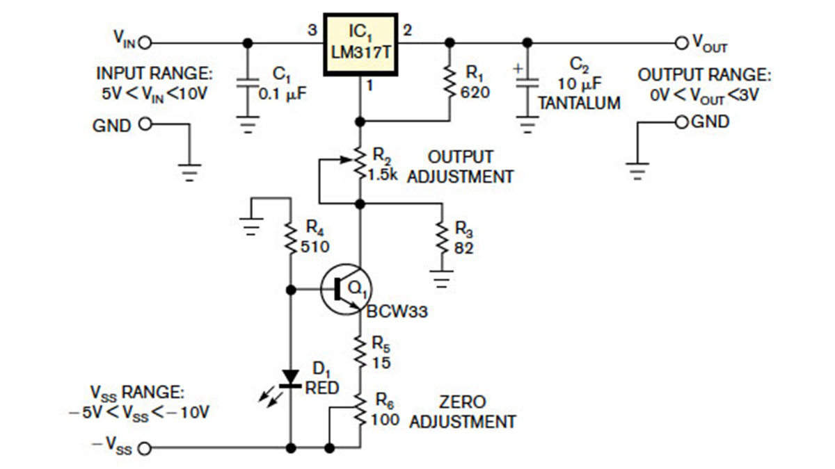
The circuit in Figure 1 incorporates foldback-current limiting to protect the pass transistor by adding feedback resistor R4. Under normal conditions, transistor Q2 doesn’t conduct, and resistors R1 and R2 bias MOSFET Q1 into conduction. When an output overload occurs, Q2 conducts, reducing the on-state bias applied to Q1 and thus increasing its drain-source resistance and limiting the current flowing into regulator IC1, an LM317. Adding R4 makes Q2‘s bias current dependent on the output voltage, VOUT, which decreases under overload conditions.
For the circuit in Figure 1, you can calculate the maximum foldover and short-circuit currents, IKNEE and ISC, respectively, as follows:
In a practical design, you select values for IKNEE and ISC and equal values for R3A and R3B and then use equations 1 and 2 to calculate resistors RSC and R4. For the circuit in Figure 1, the output’s maximum and short-circuit currents are fixed at 0.7 and 0.05A, respectively. With R3A and R3B set to 100Ω, solving the equations yields values of 0.73Ω for RSC and 4.3 kΩ for R4. You can demonstrate the circuit’s performance by applying a variable-load resistor that’s adjustable from 0 to 200Ω. As Figure 2 shows, the output’s simulated and measured voltage-versus-current characteristics, VOUT and IOUT, respectively, are in close agreement.
For More Details: Circuit adds foldback-current protection
- What is the purpose of adding foldback-current limiting to an LM317 regulator?
To reduce output current during overloads, limiting power dissipation in the pass transistor and protecting the regulator from damage. - How does transistor Q2 contribute to foldback-current limiting?
Q2 conducts during an overload, reducing Q1 bias and increasing Q1 drain-source resistance, which limits current; with R4, Q2 bias depends on output voltage so current folds back as VOUT falls. - Can you calculate RSC and R4 for desired IKNEE and ISC?
Yes; select IKNEE and ISC and equal values for R3A and R3B, then use the provided equations to compute RSC and R4. - What example values achieve a 0.7 A maximum and 0.05 A short-circuit current?
With R3A = R3B = 100 Ω, calculated values are RSC = 0.73 Ω and R4 = 4.3 kΩ. - Does adding R4 affect Q2 behavior under overload?
Yes; R4 makes Q2 bias current dependent on VOUT so Q2 reduces Q1 bias more as VOUT drops, creating foldback of output current. - What test method demonstrates the circuit performance?
Apply a variable-load resistor adjustable from 0 to 200 Ω and compare simulated and measured VOUT versus IOUT curves. - Does the foldback limiter fix the maximum output and short-circuit currents?
Yes; the circuit fixes the output maximum and short-circuit currents at the designed IKNEE and ISC values. - Why is foldback preferred over simply using higher-rated components?
Foldback reduces stress and dissipation during faults, avoiding the need for conservatively oversized components and improving reliability.