In this post, we will discuss Automated-Point-to-Point-Model-Railroad-With-Yard-Siding: Arduino microcontrollers open great possibilities in model railroading, especially when it comes to automation. This project is an example of such an application. It is a continuation of one of the previous projects.
This project comprises of a point to point model railroad layout with a yard siding to house a train. All of the operations are controlled by an Arduino microcontroller board with the help of feedback mechanism and the train and the turnout is controlled by an Adafruit motor shield.
Automated Point to Point Model Railroad With Yard Siding Steps:
Here is what you will require for the build:
- An Arduino board is compatible with Adafruit motor shield v2.3.
- An Adafruit motor shield v2.3.(Click here for more information.)
- An expansion shield(Optional, recommended to expand the +5V and GND pins of the Arduino board in order to connect the sensors.)
- 3 ‘censored’ tracks.
- 4 male to male jumper wires(2 to connect track power and others to connect the turnout.)
- 3 sets of 3 male to female jumper wires(A total of 9 wires used for connecting the 3 pins of each sensor to the Arduino board and power.)
- A 12-volt DC power source with a current capacity of at least 1A(1000mA).
- A suitable USB cable to connect the Arduino board to the computer.
- A computer to program the Arduino microcontroller.
- A screwdriver.
Program the Arduino Microcontroller
Make sure you have the Adafruit motor shield library installed in your Arduino IDE. You can get full documentation about the motor shield and the necessary software from this link.
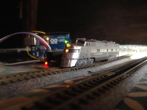
Make a Test Layout
Kato Unitrack is great for making temporary layouts, especially for testing purposes. Click on the image for more information. Make a layout as shown in the above image. The length of the track in the mainline(Between points A and B can be made of any length possible.) Make sure all the rail joints are properly made and the track rails are cleaned properly.
Install the Motor Driver Shield on the Arduino Board and Connect It to Track Power and Turnout
Install the shield carefully on the Arduino board by aligning the pins of the shield with the headers of the Arduino board. Do it gently and make sure no pins of the shield get bent.
Connect the output pins of the shield marked as M4 to the track power wires and those marked as M3 to the turnout wires. Make note that the setup is compatible with only two-wire solenoid type turnouts.
Read More