Summary of A Shuttle Mission Control Mock-Up for Kids
This article details the construction of a portable, wooden "Mission Control Center" for children to simulate a space shuttle launch. Designed as a self-contained silver box with ten functional panels, the project uses an Arduino Mega and Uno to control LED displays, toggle switches, and a sound board. The simulation guides kids through pre-flight checks, a countdown, powered flight tasks, and orbital tracking, complete with realistic audio and visual feedback to create an immersive educational experience.
Parts used in the Shuttle Mission Control Mock-Up:
- Wooden box (1/2 inch plywood)
- Silver/gray hammered paint
- Arcduino Mega
- Arduino Uno
- Adafruit Audio FX Sound Board
- Texas Instruments SN74HC595N Shift Registers (2)
- Solder-able Breadboards (2)
- Four I2C compliant 4-digit 7-segment displays
- Momentary buttons and toggle switches
- LED lights (Red/Green indicators and general purpose)
- Transformers (9VDC, 12VDC, 5VDC)
- 110 volt power strip
- Screw Terminal Strip Block
- Wire thin ribbon cable
- Piano type continuous hinge
- Lid handle and locking clasps
- Barrel slot bolts
- Adhesive backed paper graphics
- Laminated world map
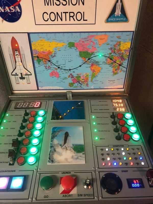
A Mission Control Center for children was constructed to manage a pretend launch of the space shuttle. I wanted to play-out the make believe mission with nothing but LED lamps to tell the story; both 7-segment displays and graphic displays with LED lights strategically mounted. I tried to keep it straight forward and sequential with required child interaction so they felt they were really directing a space shuttle mission.
The Mission Control Center is in a self-contained wooden box that is painted a silver/gray color to look like metal. This makes it easy to transport. The control center is made up of smaller panels that have specific functions or show specific information concerning the make believe shuttle launch. The whole scenario is controlled by an Arduino sketch. Some audio is also added by using a small sound board with realistic recordings that are triggered when a specific control button is pushed.
Step 1: The Scenario
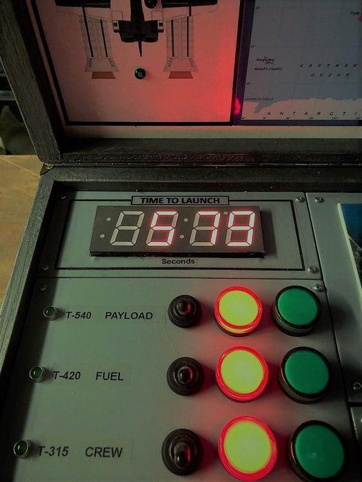
Countdown begins at 10 minutes before liftoff or T-600 seconds. During the countdown, a series of warning lights come on 10 seconds before a pre-flight system must be approved for the launch. Simultaneously, a “heads-up” display of the shuttle on the inside of the lid will visually identify the system to be checked. The child must move the associated toggle switch up to give the OK, consequently a green indicator light comes on and the red indicator light goes off. The child must repeat this for each pre-flight system approval that is alerted. There are a total of seven pre-flight system checks.
You can stop the countdown at any time by pushing the “Hold” button. Once the “problem” has been corrected, you push the countdown “Start” button again to resume the countdown from where it was stopped. Once, each pre-flight system has been checked as OK by the child, the countdown will reach zero.
At that time, the green “Go” or “Blast-Off” oversized mushroom launch button is pushed to launch the shuttle with its associated rockets and fuel tank. This “Go” button will not work until the countdown is complete (down to zero). At lift-off, a lot starts to happen:
1. A recorded NASA broadcast of a shuttle lift-off plays for about 35 seconds.
2. A couple of LED lights under the middle picture of the space shuttle launch flicker to simulate the rockets firing.
3. The child can follow the initial powered launch on the top middle map of the eastern seacoast as it leaves Kennedy Space Center (KSC) in Florida.
4. Mock flight trajectory statistics start tracking the progress of the launch (altitude, speed, mission time) on the top right panel.
In real time, powered flight lasts for about 8 ½ minutes. As with the countdown, the child has certain tasks that must be completed to simulate a successful launch. Again, a green light will come on 10 seconds before a task must be completed. I included four tasks the child should complete by throwing the toggle switch up so the green indicator light comes on and the red indicator light goes off. The four powered flight tasks are:
1. Solid Rocket Boosters (SRB) Full Throttle
2. SRB Separation
3. Shuttle Roll Up
4. MECO (Main Engine Cut Off)
The indicator lights for these tasks correspond to the top middle powered flight tracking map of the east coast of the United States that I mentioned before.
Once the shuttle achieves orbit, a child can track its path around the earth on the world map mounted on the inside of the lid. Nine tracking stations are indicated by an individual LED light. From my research, it seems the average orbit around the earth last 90 minutes at approximately 17,500 MPH. So each tracking station lights up approximately every 10 minutes as it tracks the shuttle. Once the child is satisfied with their shuttle mission, they can end the simulation at any time by pushing the red mushroom “Abort” Button.
Step 2: The Design
The overall mock-up of a Mission Control Center was made up of many smaller panels. Each panel was designed to accomplish a particular function or display a piece of information. Each panel had to be planned and laid out for the particular components that would be mounted on it. I ended up with a total of ten panels. The size varied depending on what components were attached. Each panel could be assembled and wired separately and tested to make sure it worked.
The box will be designed to hold three columns of panels. The mission control center will be laid out with pre-flight functions and information on the left side, blast-off functions and information in the center and powered flight and orbit functions and information on the right side. Graphics on the inside of the lid will give a “heads-up” display of some valuable pre-flight and flight information.
The mission box will be made out of light ½” plywood with a lid and handle so it can be easy transported. It will plug into regular 110 volt house current for the power to run it. The mission control box will be approximately 24 inches wide by 18 inches deep and 9 inches high.
Step 3: Individual Panels and Electronic Components
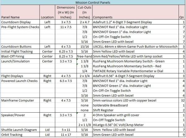
In this section each panel is listed and named for its function. The table attached will provide the dimensions of the panel, the cut-out size(s), and the electrical components that are placed in the panel
All circular cut-outs were done on a drill press. Rectangular and odd shaped cut-outs were done with a portable jig saw. The panels were sanded smooth and then painted a machine gray color and set aside to dry.
Other components used that were not listed above:
· 10 wire thin ribbon cable
· Arduino Mega
· Arduino Uno
· Solder-able Breadboard (2)
· Sound Board (Adafruit Audio FX Sound Board)
· Texas Instruments SN74HC595N Shift Registers (2)
· Misc 24 gauge wire and connectors
· Power Strip (110 volts)
· Screw Terminal Strip Block (for 12 VDC)
· Transformers
o 9 VDC – for Arduino (2)
o 12 VDC – for Red/Green Indicator Lights
o 5 VDC – for Sound Board
Step 4: Bench Set-Up
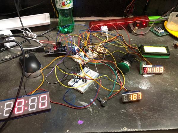
I needed “proof of concept” reinforcement to make sure the Arduino code and electronic set-up would work before starting the final assembly. A bench set-up was completed as shown in the accompanying photos. Multiple solder less breadboards and jumper wires were used to make all connections. I had four I2C compliant 4-digit 7-segment displays hooked up to pins #20 (SDA) and #21 (SCL).
Arduino can communicate with many devices in I2C, but each display must be set to a different address. On the backpack of the Adafruit display the address can be adjusted by solder jumpers. This was done so each display had a different address. The LED lights and momentary buttons were hooked up to the pins on the Arduino Mega in the usual way. After many trails and errors in the Arduino code, I was able to get the Mission Control sketch (Version 7) to run without interruption. I will discuss the Arduino sketch in another section.
In addition, did a bench set-up to perfect the shift registers I was going to use in the “Mainframe” computer. I had never worked with the Adafruit soundboard before, so I also did a bench set-up to understand how it worked before I mounted it in the Mission Control Center.
Step 5: Box Construction
Since I am posting this Instructable under the Circuits/Arduino category, I will not go into great detail on the construction of the Mission Control box. The woodworking skills are pretty fundamental and any designed box made to the correct dimensions should work.
So as backward as it sounds, I made the cabinet box for the Mission Control Center after I designed all the panels. I wanted to make sure the panels could be positioned correctly. I essentially had 3 columns of panels so all panels will be the same width. I wanted the total box width to be 2 feet or 24 inches. If you subtract the ½” thickness of each box side, the total functioning control layout will be 23 inches wide. Dividing that number by 3 and allowing for some leeway for positioning, the width of the 10 panels should be 7 1/2″ inches. The total depth of the control layout will be approximately 18 inches.
I made the height of the box approximately 7 inches with a slant from back to front so components on the control center could be seen clearly. The front height was a little over 4 inches high. This would give enough height for all the electrical components to be mounted safely below the control panels with enough room to make all the necessary electrical connections.
The lid was fabricated with slightly less depth then the box. This will give a resting platform for the lid so it does not fall completely back when it is opened. Some important shuttle tracking information will be placed on the inside of the lid to serve as a kind of “heads-up” display for the make believe shuttle mission. The lid is made approximately 2 inches in height to accommodate the display panel with its LED light placements and the corresponding wire connections.
Once the lid and base of the box were completed it was painted with gray “hammered” paint. This made the plywood look and feel like metal. A piano type continuous hinge was used to secure the lid to the bottom of the box. A handle and locking clasps were placed on the front side of the box. Two barrel slot bolts were mounted on the back of the lid to engage the bottom box when the lid was up. This will prevent the lid from accidently coming down on someone’s hands. See the attached photos.
Step 6: Final Assembly
On the lower panel with the speaker is the main power On/Off toggle switch. The two connections on the switch are spliced into one side of a 110 volt power cord coming into the bottom of the cabinet box. A multi-outlet power strip is plugged into the cord. All the DC transformers are then plugged into the power strip. This allows them to all be switched on at the same time controlling all the PCB boards.
What took the most time was assembling each individual panel. All switches, LED lights, 4-digit 7-segment displays, graphics, momentary buttons and any other components were secured to the appropriate panel. Each panel was then wired up separately and tested on my bench top set-up.
I want to make mention of the “mainframe computer” panel. My plan was to have a bunch of LED lights randomly flashing to simulate the inner workings of a powerful computer, like portrayed in old science fiction movies. However, this would have taken up a lot of pins on the Arduino. I ran across an idea of using a shift register to control the flashing of the LED lights so fewer pins would be needed on the Arduino. I found a DYI article on the internet that explained how to configure the shift resisters. Each shift register can control 8 LED lights with only 3 connection wires to the Arduino. I ended up placing two shift registers on a solder-able breadboard and double soldering 2 LED lights to each shift register pin. That gave me a total of 32 LED lights that were laid out in a 4 row x 8 column configuration. See the attached photos. It looks like a “hot” mess but it really works well.
Just a side note. As it turned out, I decided to use a separate Arduino Uno to control the 32 LED lights. I was a little worried about the power consumption all these lights used. Also, a separate Arduino sketch was modified to control the random blinking. A single momentary button was used to turn the “mainframe computer” on and off. This button is located on the Countdown Button Panel.
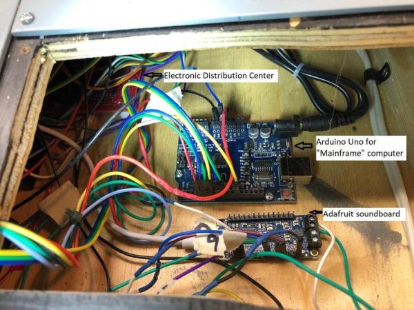
Next, I needed a way to manage all the electronic connections from the various panels. I came up with the idea of a centrally located “electronic distribution center”. This was made with various pin connections soldered to a perforated breadboard. For example, I had four I2C compliant 4-digit 7-segment displays that all needed a connection to pin #20 (SDA) and #21 (SCL) on the Arduino Mega board. Soldering male connection pins to common breadboard electrical paths made the multiple connections much cleaner. I could then just run two pinout wires from the breadboard to the #20 and #21 pins on the Arduino board.
The distribution breadboard also allowed a central area to connect all ground and 5 VDC wire connections. A separate screw terminal block was used to connect all 12 VDC lights to the appropriate transformer. Most of the momentary buttons were wired directly to the corresponding Arduino or Sound Board Pins. I made custom shields for the Arduino Mega so the jumper wires could be screwed down for better retention.
The sound board from Adafruit Industries was incorporated into the design to give some real life sounds to the Mission Control Center. This sound board can hold up to eleven different .WAV files. The lift-off sound clip from the NASA Discovery launch adds a lot of realism to a child’s experience when they push the “Go” button.
All electrical components were mounted to the plywood floor of the mission control box. This included the:
· Arduino Mega
· Arduino Uno
· Adafruit Sound Board
· Breadboard Distribution Center
· Screw Terminal Block
The 110 volt power strip was mounted at the back of the box.
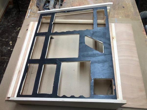
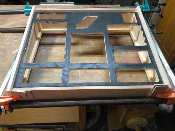
A ½” thick plywood framework was cut out to provide clearance for the electrical components. This framework will match the final layout of each panel. As each panel was attached with four #4 size wood screws, each panels electrical connections were attached centrally to the appropriate Arduino pin, power supply or the electronic distribution center. See the attached photos.
The last thing to assemble was the lid components. One large lid panel was cut to fit the inside dimensions of the lid. Again, 1/8” thick hardboard was used for this and painted a snow white color. A graphic outline of the shuttle and its attached launching components was found on the internet and printed on adhesive backed paper. A laminated world map was purchased from Amazon. The shuttle diagram was placed on the right side of the lid above the pre-flight panels controls and the world map was placed to fill the rest of the width of the lid panel. Various mission control and NASA decals were placed above these displays.
I placed LED lights on the shuttle diagram that corresponded to the pre-flight system checks on the control panel. They will light up the same time as the control panel LED action lights.
An approximate orbit of the shuttle was drawn on the world map with a black Sharpies pen. I did not research all the tracking stations; I just placed 9 LED lights equally spaced apart so the child could track the progress of the shuttle in orbit. The LED light leads for both the shuttle diagram and the world orbit tracking map were brought to the electronic distribution breadboard under the control panel by way of thin ribbon cables.
Source: A Shuttle Mission Control Mock-Up for Kids
- How many pre-flight system checks are included in the simulation?
There are a total of seven pre-flight system checks that the child must approve. - Can the countdown be paused during the mission?
Yes, the countdown can be stopped at any time by pushing the Hold button. - What triggers the NASA broadcast audio during the launch?
The recorded NASA broadcast plays when the green Go or Blast-Off mushroom button is pushed after the countdown reaches zero. - How many tasks must be completed during powered flight?
The child must complete four specific tasks: SRB Full Throttle, SRB Separation, Shuttle Roll Up, and MECO. - How long does it take for each tracking station light to activate in orbit mode?
Each tracking station lights up approximately every 10 minutes to simulate the shuttle's progress. - Why were shift registers used in the Mainframe computer panel?
Shift registers were used to control 32 LED lights while using fewer pins on the Arduino. - What separates the mainframe computer LEDs from the rest of the system?
A separate Arduino Uno was used to control the 32 flashing LED lights for the mainframe computer. - How many different WAV files can the Adafruit Sound Board hold?
The sound board can hold up to eleven different .WAV files. - What material was used to construct the control center box?
The box is made out of light 1/2 inch plywood painted to look like metal. - How is the lid secured to prevent accidental closure?
Two barrel slot bolts mounted on the back of the lid engage the bottom box when open.