USB data-acquisition modules offer good value and ease of use, which makes them an attractive choice for manufacturing test. But before you use the modules in a manufacturing test system, you need to take steps to protect them. During manufacturing test of circuit boards or subassemblies, a defect in an assembly may result in a condition that damages a data-acquisition module.
The typical USB DIO (digital I/O) module uses a set of 8-bit bidirectional tristate ports. Figure 1 shows a typical circuit that we test with one of those ports. We use one digital output pin from the USB module to drive the circuit and one digital input pin to read the circuit’s response. If the circuit works properly, we expect to see a clean digital signal from the circuit. For a circuit coming off the manufacturing line, however, the digital input pin of the DUT (device under test) could be shorted to ground, shorted to VCC, or shorted through some low impedance to a higher voltage. Any of these conditions can damage the USB module’s input pin.
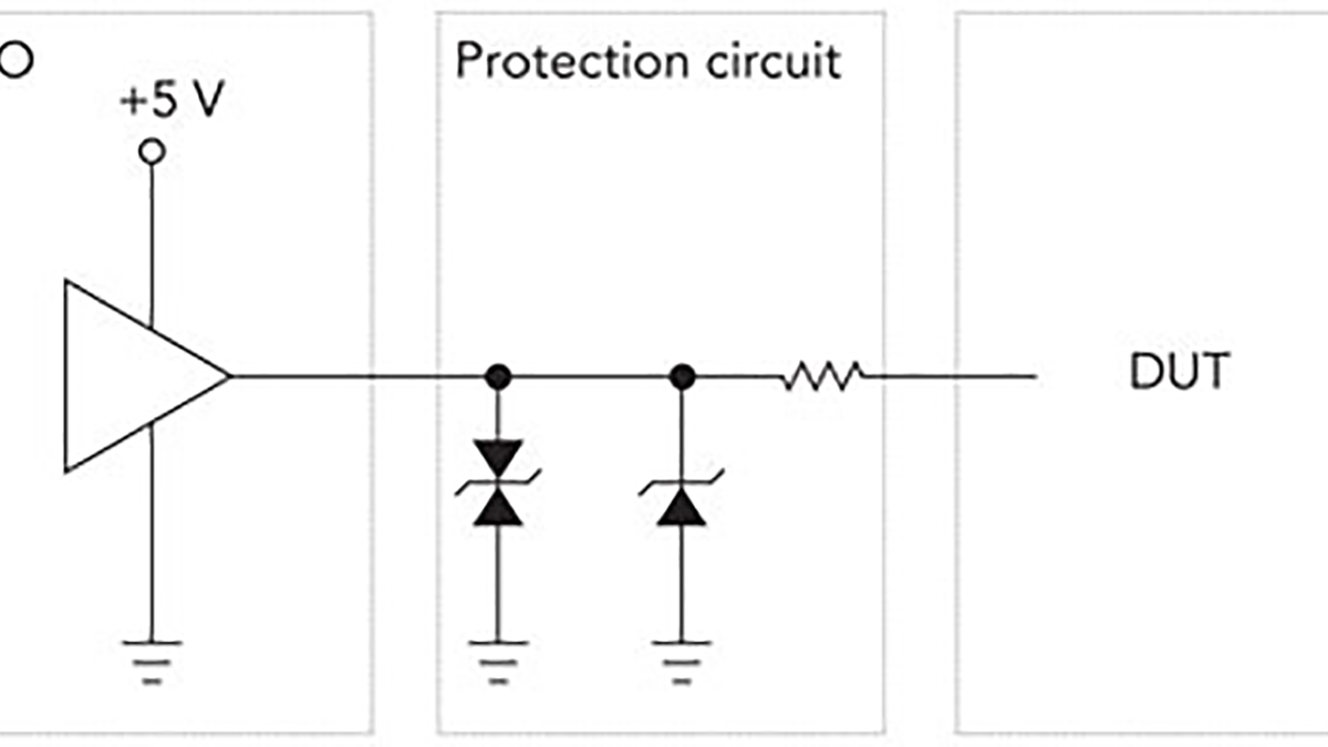
If there’s a short across the 2-k resistor from the collector to the +15-V supply, that voltage will appear at the USB module’s input pin, which could damage it. To avoid such damage, we add protection circuits between the DUT and the USB module (Figure 2).
For More Details: Test Ideas: Protect USB measurement circuits