Subject purpose:
This tutorial is at the introductory level. Focus on recording how the Arduino microcontroller and the stone display screen link and use. One in order to beginners can quickly get started, and also for the second time when unfamiliar can quickly find.
Hope to achieve: the more detailed the better, so that most of the small partners who do not understand the STONE serial screen products and the Arduino microcontroller can follow the steps can operate the kind of detailed description. Every step is clear. How to download and what to do next. Follow the instructions in this tutorial, put my code in, and restore the project to the kind that works.
There are a lot of Arduino tutorials online that fail…… There are plenty of examples available on GitHub. The first step stumbles most beginners.
Therefore, this time to “point-and-shoot camera” recording. Some engineers “warrior” said that (Arduino) children just play, let him use Arduino to do projects, is to insult his personality, ha ha…… This article entry level, is not aimed at these “warrior” write oh!
Hardware preparation:
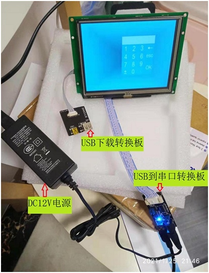
1. Serial port touch screen STVI056WT-01. With USB to serial port conversion board, USB download conversion board, supporting the connection cable, as shown in Figure 1.
2. Adapted DC12V power supply. You can go to the electronics city to buy it, or you can use the power supply of the TV set top box at home to confirm the voltage and current (preferably 2A). You can plug in the USB to the serial port conversion board, as shown in Figure 1.
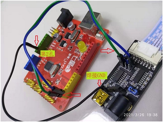
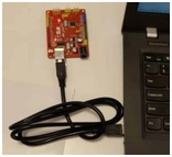
3. Red Arduino development board. The model is LY-F2 of Seven Star Bug, which comes with USB cable for power supply. As shown in figure 2.
4, electric iron. When buying Arduino development board, remember to provide some connecting wires. TX and RX lines of serial ports should be connected, and GND should be welded. As shown in figure 2.
5, commonly used DC5V power supply. This will be available, because you can use the charger, mobile phone charger, computer USB charging socket oh.
Tutorial Directory:
1. Hardware connection;
A) Connect the Stone screen, USB to serial port conversion board, USB download conversion board;
B) Connect USB to the serial port conversion board and Arduino development board communication line;
C) Connect DC12V and DC5V power supply;
2. Software installation
A) Installation of Stone serial port screen related software;
B) Installation of Arduino development board software;
3. How to make both the screen and the Arduino move?
A) Make the STONE serial port screen move;
B) Get the Arduino development board moving;
C) Let Stone serial port screen and Arduino development board communicate and interact.
Next, document the process.
1. Hardware connection.
A. Connect the Stone screen, USB to serial port conversion board, USB download conversion board
Connection Instructions: USB to Serial Switch Board is the longer board with DC12V power socket JP1 on it. The STVI056WT-01 serial port touch screen is used. The two cables in Figure 1 are provided by the government. The socket behind the screen is also “anti-stupid”.
The conversion board from USB to serial port needs to be connected to the DC12V power supply, which is not allocated by the government. You need to buy it by yourself. The core wire is positive! My own DC12V power supply is 2A current, ready-made TV set-top box power supply at home, the effect is very good.
The Stone TFT LCD module is simple to download and use.
B. Connect the USB communication line to the serial port conversion board and the Arduino development board
You can take off the USB to serial port conversion board near the row of a jumper, with 3 lines (need to move the electric iron, because the USB to serial port conversion board does not have GND lead point —– hope that the official STONE can improve it, it is best to also give 3 serial port connection line, now we can only go to find.
I’m ok, there is inventory, and the advanced “silly white sweet” may be embarrassed oh, it is better to buy Arduino development board with some!) Figure 2 Connection. The black GND line is soldered firmly along the soldering pad of the USB socket with an electric soldering iron, and the second hole at the position shown in the illustration on the other end (the corresponding hole position on the board is marked with GND); The green and blue lines should be inserted correctly, not backwards. The USB to serial port conversion board is shown in Figure 2. The blue line is connected to the upper right pin and the green line to the lower left pin (the jumper short connection here has been removed!). The red Arduino development board, the model of which is Ly-F2 of Seven Star Bug, is shown here as shown in Figure 2. The green is R0X and the blue is TX, which should be marked.
Aggressive “silly white sweet” people, come on!
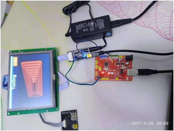
C. Connect DC12V and DC5V power supply
The USB to serial port conversion board is equipped with an official USB cable. The Arduino development board is also equipped with a USB cable when purchased. The DC12V power supply is its own, so it can be connected as shown in Figure 3. My own DC12V power is plugged directly into an AC220V socket, and the two USB cables delivered require a DC5V converter, which works with most phone chargers. So, this step is not what difficult (should have 2 mobile phone charger, or charge treasure always should have, ha ha…… You can also plug in a USB port on your computer that charges your phone!)
2. Software installation.
Into the STONE’s official website: https://www.stoneitech.com/support/download/software download below official seal to specify software;
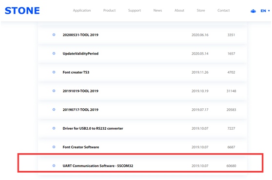
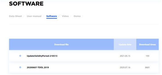
Unpack the first, get SSCOM32 serial communication software (not introduced in this description, but your own learning, you can use it to debug the effect). Of course, many people have their own familiar serial port tools, I still like the official recommendation, compatibility, reliability is guaranteed.
Unzip the second Tool, is the official Tool 4.3 software, unzip, find tool4.3. exe, can be directly used. All English, a little inconvenient, use the translation software! The detailed functions of this tutorial are not introduced, the back will be directly informed to start using —– straight into! To understand the details of the enthusiasts can browse the official tool manual —-, but only the old version, hope the official can be updated in time!
We’ll download the Stone DEMO directly to make it easier to get started. This tutorial is also described as such.
Download the 640×480 Test Project DEMO with the official seal in accordance with the STVI056WT-01 screen. The download page is as follows:
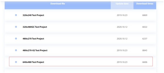
Remember to decompress and reserve after downloading.
B) Installation of Arduino development board software;
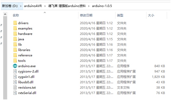
Please ask the customer service of Taobao for the information provided by the official development board. After downloading and decompressing, there is the Arduino-1.0.5 directory. Click the Arduino. exe in the official seal of the directory to start the development environment.
In Figure 4, the directory contains libraries, routines, arduino.exe, and more. This tutorial is not detailed, enthusiasts can go to the Arduino website to learn. The following will also be straight, direct access, ha ha…… The official website is very comprehensive, very detailed, and then the introduction is redundant. Our focus: getting started, getting started, and enjoying the joy of success!
Note: The version of Arduino-1.0.5 listed in this tutorial does not represent eternity, because versions will be updated irregularly. Please do the necessary homework according to the new version when you use it.
3. How to make both the screen and Arduino move?
A) Make the STONE serial port screen move;
Step by step as follows;
1. The USB terminal of the computer is connected to the square “USB download and conversion board” through the USB cable attached with the Stone. The diagram below:
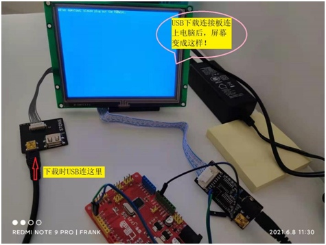
At this point, “After Download, Please Plug out the USBMini” is displayed at the top of the screen, indicating that the serial port screen is ready to receive the downloaded program.
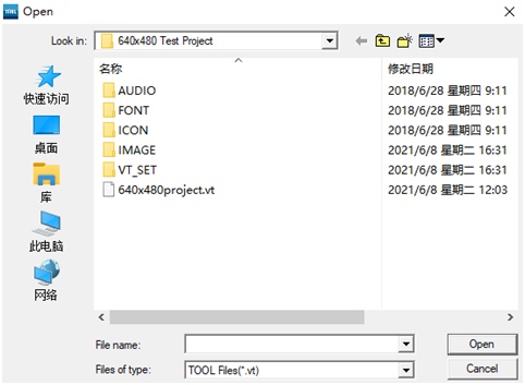
2. Open Tool4.3 on your computer, using File (F) menu —- “Open (O)… Open the file “640x480Project.vt” of the 640x480Test Project that was just downloaded and unzipped. As shown in the figure below, official seal identification project:
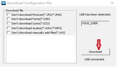
3. For the 640x480Test Project, select “Generation Configuration File” from the menu “Tool (T)” —–. Go to —– under Tool (T) and Download the Configuration file.
Note that in the Download Configuration File window below, the check boxes are unchecked. The “Download” button in the red arrow is gray if the USB Download board is not connected properly. Only when the connection is right, can you click and start downloading. There are detailed tips for downloading in the blank space. Click “X” to close it when you are finished.
When the blank area shows “Download all files successfully”, unplug the USBmini cable from the USB download conversion board, at this time the STONE screen can already move! Now you can touch it (all places can try oh, later can also be connected with the arduino communication effect for comparison), feel the joy of their own success!
Beginners can celebrate and reward themselves for making it this far for the first time, you’re great! I believe that to get here successfully, touch and see the results of victory is by no means something that ordinary people can do in one go! They must have encountered a lot of difficulties and hardened their natures even when they got here!
The next step is the use of the arduino development board and communication with the serial screen, which can be the second step, after digesting the previous and being able to learn by example, then come to the advanced stage. Of course, if you are in a hurry, you can also continue with the following.
B) Getting the arduino development board moving.
step by step as below.
- connect the computer USB to the arduino development board with the official USB connection cable included, as follows.
2. click on the arduino.exe program in the arduino-1.0.5 directory after unpacking, see Figure 4 above, to start the development interface.
3. click on the menu File—>Examples—>01.Basic—>Blink as shown below to read in the routines.
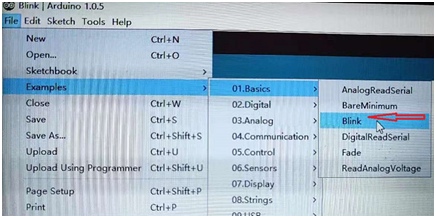
This routine is simple and easy to demonstrate, the LED is ready-made on the board, eliminating the need to build and connect the circuit, and the blinking time is easy to adjust, simple and intuitive. Through this routine, newcomers can learn to open the file, compile, modify, upload, and also familiar with the basic syntax of arduino, very good! Let the beginner do not have to find components, do not have to wiring, you can start directly.
4. Here you can modify the delay parameter in the routine to change the time of LED blinking, as follows.
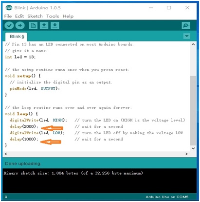
Note: In the arduino development environment, edit the code to use plain English half-angle entry mode, pay special attention to punctuation, otherwise it may be wrong! Beginners had better use copy and paste to edit, update values and symbols, etc. first!
- click on the button in the orange position in the figure below to check, validate and compile.
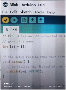
This check, validate, and compile operation can also be done via the menu SKetch—>Verify/Compile. If no error is reported, you can proceed to the next step.
6、Click the orange button in the picture below to Upload; please check in advance that the arduino development board is connected to the computer, the USB to serial conversion board has been connected to the DC12V power supply and USB power supply, the blue and green serial cable can be removed.
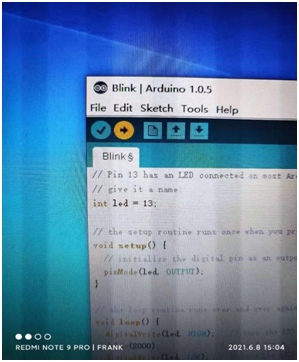
You can also use the menu File — “upload to achieve the upload operation.
7, after doing the above, if no error is reported, you can enjoy your results, enjoy the fun again! The red LED on the development board is flashing according to your modified parameters! You can modify different blinking parameters, repeat the compilation, upload, and then compare the different effects.
At this point, the serial screen has moved, and the development board has moved! The next step is to prepare and program the two communication interaction.
C) Make the STONE serial screen and the arduino development board communicate and interact with each other.
step by step as follows.
1, first look at the serial port baud rate and command word format of the header settings. The following figure.
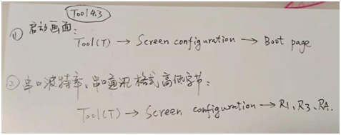
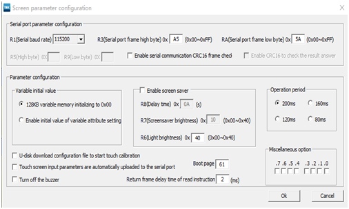
From the Tool4.3 menu item Tool (T), select Screen configuration to bring up the above Screen parameter configuration window. configuration” in the upper part of the window, there are R1, R3, RA, respectively, set the project’s serial port baud rate, command format of the head high and low bytes (such as the example of baud rate 115200, R3 = 0xA5, RA = 0x5A). Later we can ensure that their serial port can also be set to follow the product design rate, instruction format head programming! As the front we are directly to STONE DEMO compile, download, without any modification, so the following arduino environment programming, all should be in accordance with STONE DEMO’s original baud rate parameters and command word head characters to maintain consistency.
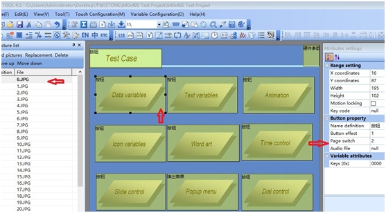
2, to arduino development board to send data to the serial screen, we can first understand the address of the serial screen variables. Open Tool4.3 tool, click the red arrow at the “0.jpg”, “Data Variables” in turn, see the button “Data Variables ” link page “2”, and then click “2.jpg”.
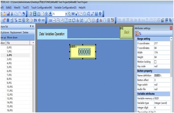
In page “2”, the following figure, click on the variable data input, the right to see the DataVariables Variables address is 0x0020; —- to write values to this address, you can see the desired display in this page Oh!
4, repeat the above operation, you can get Word ard in the page “16”, its data entry Variables address is 0x0160; Slide Control in the page “18”, its Data entry Variables address is 0x0180.
5, according to STONE’s serial data writing instructions, respectively, to the above three addresses (0x0020, 0x0160, 0x0180) to write the value of 0x0001 instruction format is as follows (including the above access to the header characters A5 5A)
A5 5A 05 82 00 20 00 01 (Data Variables write 1)
A5 5A 05 82 01 60 00 01 (Word ard write 1)
A5 5A 05 82 01 80 00 01 (Slide Control write 1)
6, according to the arduino function definition, the above instructions can be written as follows.
Serial.write(0xA5); //”A5″ is the header character.
Serial.write(0x5A); //”5A” is the header character.
Serial.write(0x05);
Serial.write(0x82);
Serial.write(0x00); // Address of the data variable
Serial.write(0x20); // Address of Data Variables
Serial.write(0x00);
Serial.write(0x01);
// —————————————————————–
Serial.write(0xA5); // “A5” is the header character
Serial.write(0x5A); // “5A” is the header character
Serial.write(0x05);
Serial.write(0x82);
Serial.write(0x01); // The address of Word ard
Serial.write(0x60); // Address of Word ard.
Serial.write(0x00);
Serial.write(0x01);
// ————————————————————————-
Serial.write(0xA5); // “A5” is the header character
Serial.write(0x5A); // “5A” is the header character
Serial.write(0x05);
Serial.write(0x82);
Serial.write(0x01); //address of slide control
Serial.write(0x80); //address of slide control
Serial.write(0x00);
Serial.write(0x01);
7, in the arduino development interface, menu File — “New, new file frank2.ino, the above three variables address recursive writing (recursive step value can be adjusted within the range specified), the period of 1 second (can be adjusted within the specified range), so it is convenient to see the effect of change. See the recorded video for details.
8, you can modify the arduino program incremental step value, compile again, upload, observe the modified effect. Note: Make sure all the connections are connected correctly as described in “Hardware Connection” above! Here, because the program of arduino development board is only modified, so the computer USB connects to the arduino development board, on the one hand, to supply power to the arduino development board, on the other hand, to update and download the modified arduino program at any time, while the DC5V power supply from USB to serial converter board should be connected to DC5V power supply of cell phone charger, rechargeable battery, etc.
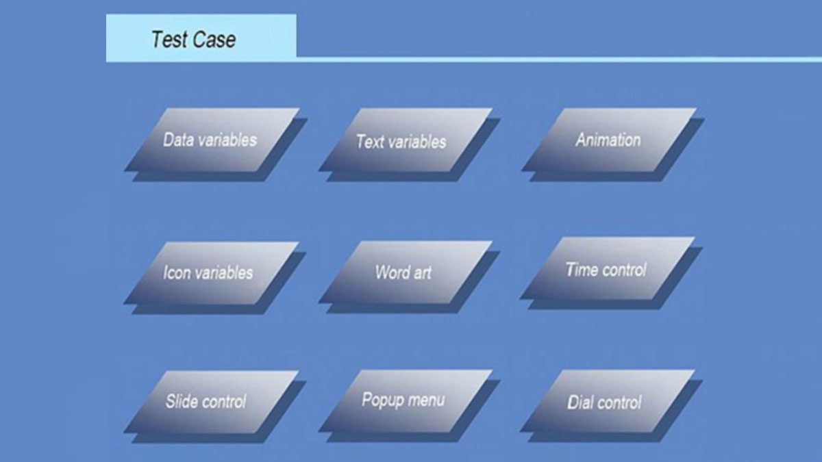
Recorded video description: video from Tool4.3 tool software open STONE DEMO compilation, download, there are hardware connection, software use, and demonstrate the effect of the touch screen after download (manual touch, including the three pages that need to be compared later — Data Variables, Word ard, Slide Control), then recorded arduino development environment compilation, upload, directly using the communication program we prepared (in the example program Blink based on the addition of communication module), this program has of course included the code of LED blinking, you can see the LED blinking. There is a video connecting the communication line between the serial screen and arduino, after connecting the USB to the DC5V power supply of the serial converter board, we can see the data transfer from the arduino to the serial touch screen. programmed step value in incremental). This completely shows the actions of the serial touch screen, the blinking LEDs of the arduino board, and the data transfer actions of the arduino board to the serial touch screen. The video was recorded in about 7 minutes or so. From the video, it is obvious that the computer screen has flickering, but STONE’s touch screen STVI056WT-01 does not have similar flickering phenomenon, is this the technical advantage of STONE? If so, kudos to STONE!
I believe this recorded video can make up for the lack of many text descriptions, if there is something in the description that cannot be reviewed, please contact me, thank you!
The development board arduino source code is transcribed as follows.
/*
frank2
STONE and arduino COMM
Turns on an LED on for one second, then off for one second, repeatedly.
The address 0x0020 is ardress of Data Variables;
The address 0x0160 is ardress of Word art;
The address 0x0180 is ardress of Slide Control;
This example code is in the file of frank. On 20210608 shenzhen China
*/
// Pin 13 has an LED connected on most Arduino boards.
// give it a name:
int led = 13;
int iData = 1; // for Data variables
int iSlide = 2; // for Slide Control
int iWord = 1; // for Word ard
// the setup routine runs once when you press reset:
void setup() {
// initialize the digital pin as an output.
pinMode(led, OUTPUT);
Serial.begin(115200); // Open the serial communication function and wait for the serial port to open, the baud rate is the same as STONE setting
while (!Serial) {
; // wait for serial port to connect. Needed for Leonardo only
}
}
// the loop routine runs over and over again forever:
void loop() {
Serial.write(0xA5); //”A5″ is the header character
Serial.write(0x5A); //”5A” is the header character
Serial.write(0x05);
Serial.write(0x82); //Write command
Serial.write(0x00); // The address of Data Variables
Serial.write(0x20); // The address of Data Variables
Serial.write(0x00);
Serial.write(iData);
digitalWrite(led, HIGH); // turn the LED on (HIGH is the voltage level)
delay(500); // wait for a half second Adjustable range:200-2000
iData+=1; //Step value of 1, adjustable observation effect Range 1-20
iSlide+=10; //Step value of 10, adjustable viewing effect Range 1-20
iWord+=1; //Step value of 1, adjustable observation effect Range 1-20
if(iData>=99) iData=1; //Setting change range
if(iSlide>=230) iSlide=2; //Setting change range
if(iWord==230) iWord=1; //Setting change range
digitalWrite(led, LOW); // turn the LED off by making the voltage LOW
delay(500); // wait for a half second,Adjustable range:200-2000
Serial.write(0xA5); //”A5″ is the header character 165
Serial.write(0x5A); //”5A” is the header character 90
Serial.write(0x05);
Serial.write(0x82); //Write command
Serial.write(0x01); // The address of Slide
Serial.write(0x80); // The address of Slide
Serial.write(0x00);
Serial.write(iSlide);
Serial.write(0xA5); //”A5″ is the header character 165
Serial.write(0x5A); //”5A” is the header character 90
Serial.write(0x05);
Serial.write(0x82); //Write command
Serial.write(0x01); // The address of Word art
Serial.write(0x60); // The address of Word art
Serial.write(0x00);
Serial.write(iWord);
}
article source: